MD280/MD280N User Manual Parameter Description
- 125 -
Group F2 Input Terminal
MD280 series inverter has 5 multifunctional digital input terminals (DI1 to
DI5), of which DI5 can be used as high-speed pulse input terminal, and
ME280 series inverter also has two analog input terminals (AI1 and AI2).
Caution:
1: When DI5 as high-speed pluse input terminal,set function setup of input
terminal DI5 to zero(no function)so as to avoid malfunction. When DI5 is
high-speed pluse input, it can be the frequency source, Frequency source
upper limit, PID setup source, PID feedback source, and setup source of
MS zero-segment.
2: For the counter input and the length count input, please use DI5 when
the pluse frequency is higher.When use low-speed pluse, and use DI1 to
DI4.
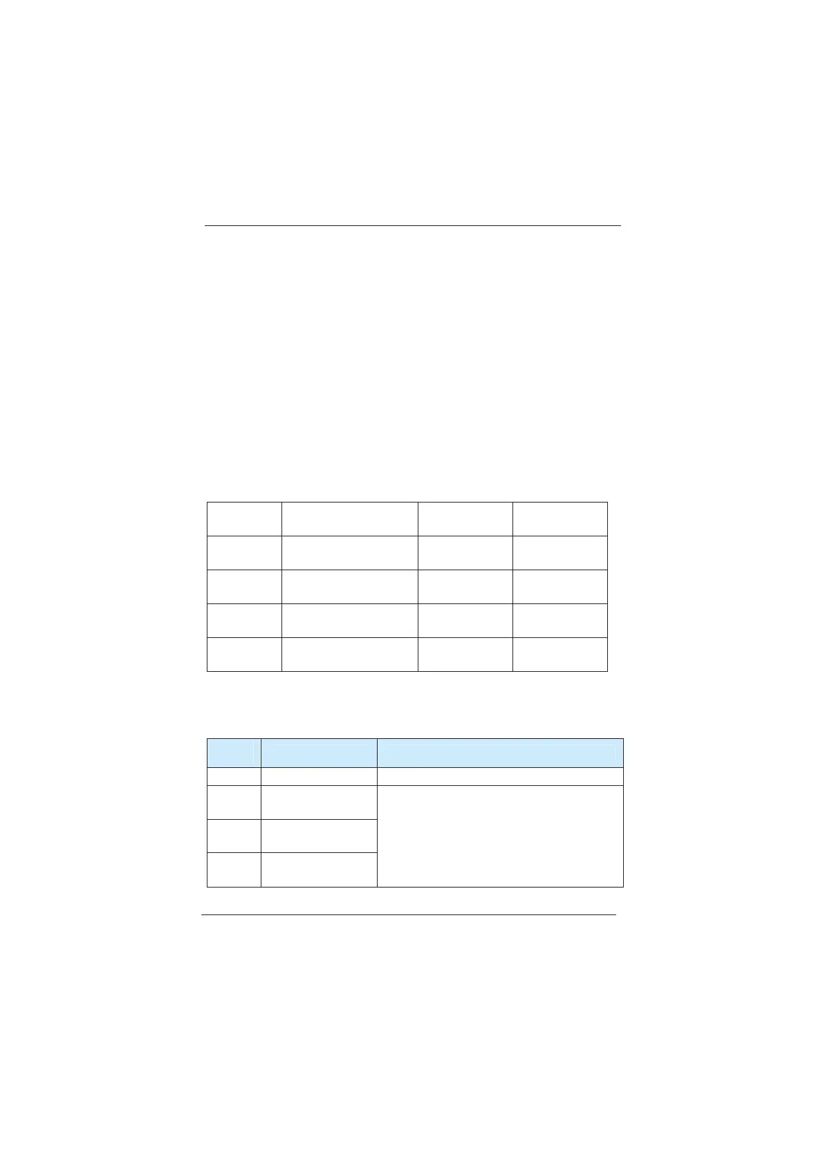
F2-00
DI1 terminal function
selection
Factory
default value
1(Forward
rotation)
F2-01
DI2 terminal function
selection
Factory
default value
2 (Reverse
rotation)
F2-02
DI3 terminal function
selection
Factory
default value
4(Forward
rotation Jog)
F2-03
DI4 terminal function
selection
Factory
default value
8(Free stop)
F2-04
DI5 terminal function
selection
Factory
default value
0(No function)
Parameters below are used to set the corresponding functions for the
digital multi-purpose input terminals. Functions of DI terminal could not be
selected repeatedly except zero. If a function is unable to be selected,
please check whether the function has been selected by other terminals.
Setup
value
Function Description
0 No function The input terminals have no function.
1
Forward rotation
˄FWD˅
2
Reverse rotatio
˄REV˅
3
Three-line running
control
When command source (F0-00) is set as
“terminal command channel”, forward or
reverse running of the inverter will be
controlled via the external terminal.Refer
to description of functional codes of group
F2-06 for the settings of forward and
efesotomasyon.com
 Loading...
