Operation and Display MD280/MD280N User Manual
- 62 -
Chapter 4 Operation and Display
4.1 Introduction to Operation and Display Interface
Modification of function parameter, monitoring of inverter operation, control of
inverter operation (start and stop) can be performed through the operation
panel.
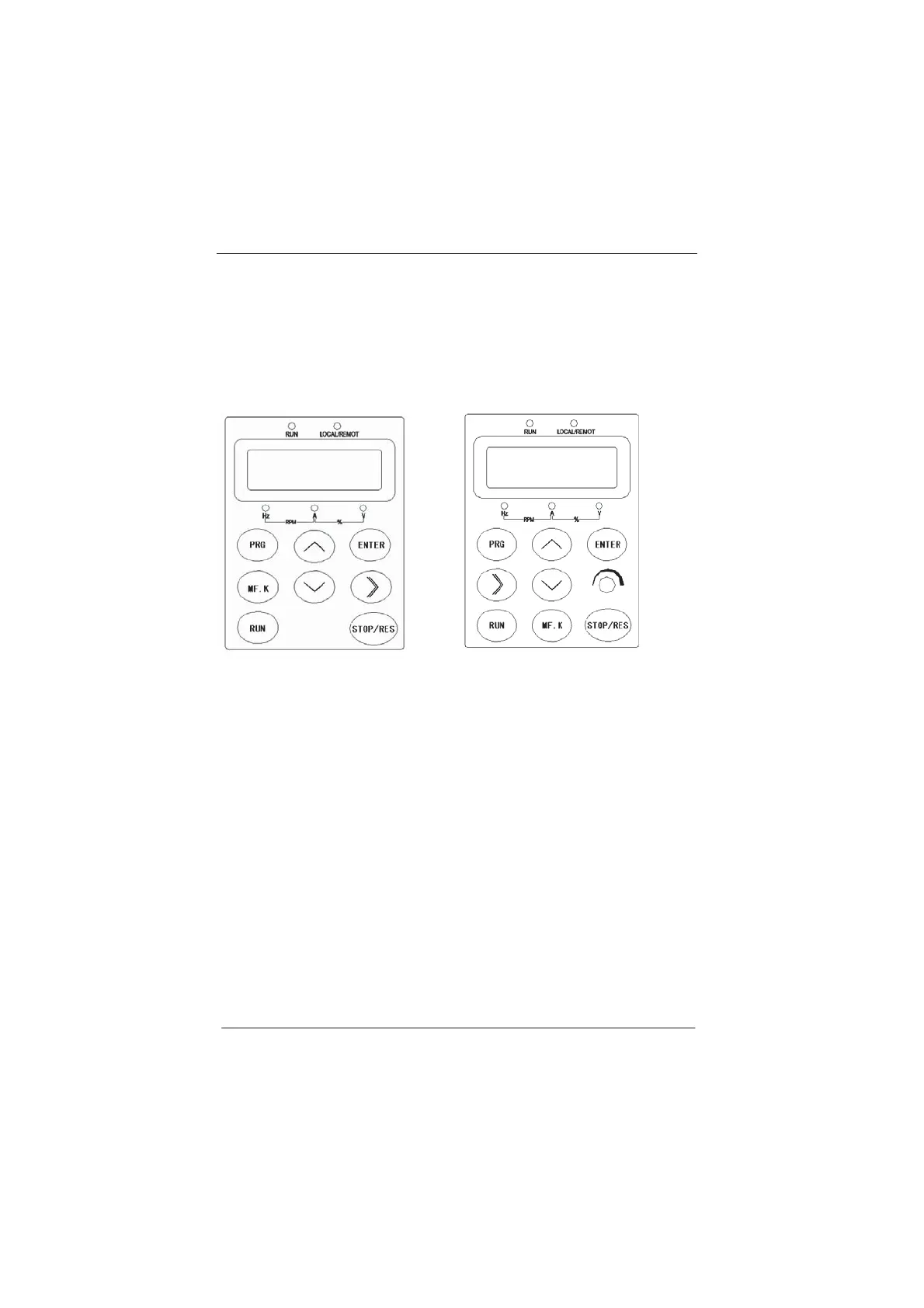
Fig.4-1 Schematic Diagram for the External Operation Panel of Inverter without
Potentiometer
Fig.4-2 Schematic Diagram for the External Keyboard of Inverter with
Potentiometer
1) Function LED Indictor Description:
RUN: When it is OFF, it indicates that the inverter is in stop status. When it is
ON, it indicates that the inverter is in running status.
LOCAL/REMOT: The LED indicator for keypad operation, terminal operation
and remote operation; when it is OFF, it is under keypad operation control;
when it is ON, it is under terminal operation control; when it flashes, it is
under communication operation control.
2) Unit LED indictor description:
Hz refers to unit of frequency
A refers to unit of current
V refers to unit of voltage
efesotomasyon.com
 Loading...
