1. Product Information
- 9 -
1
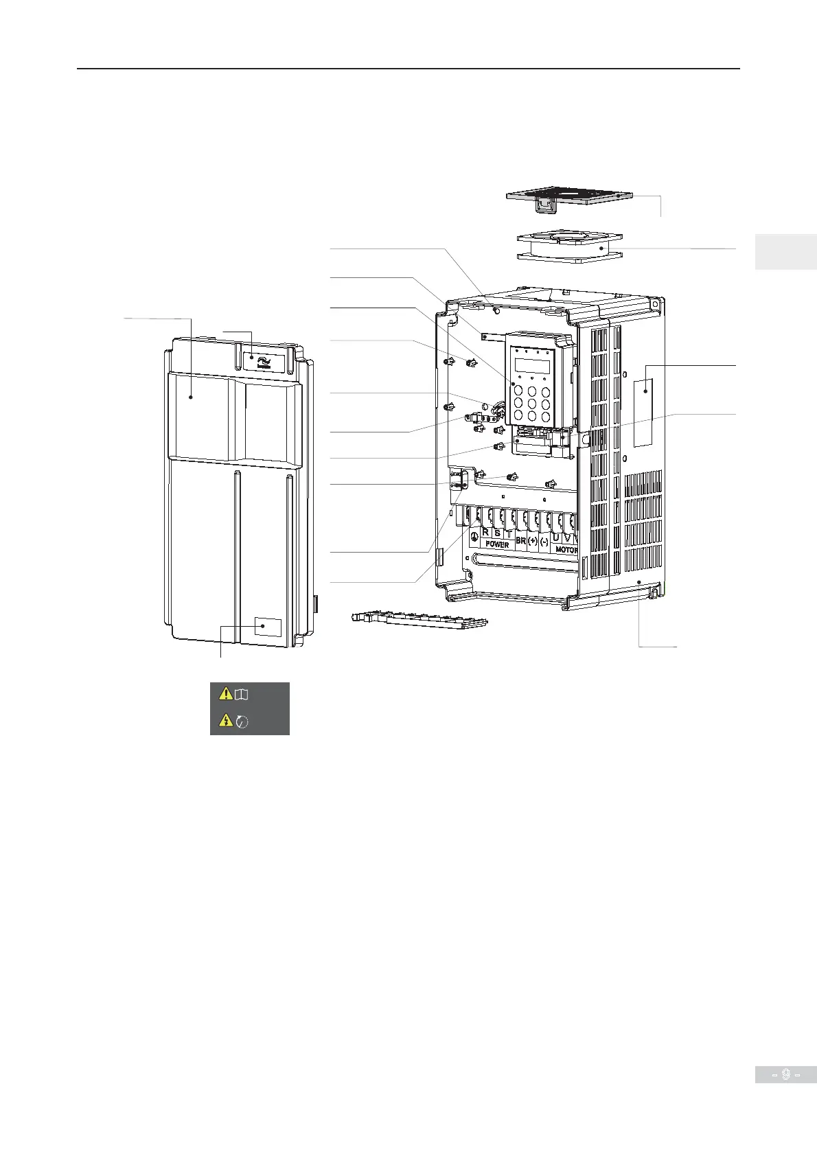
1.2 Internal View of MD290
The drive can have either a plastic housing or a sheet metal housing, depending on the power rating.
Figure 1-2 Internal view MD290T18.5G/22P to MD290T37G/45P (plastic housing)
Housing
Cable support bracket
Logo
Warning label
Read the user guide of the AC drive carefully before installation or operation.
Do not remove the front cover while the power is on or within 10
minutes after the power is turned off.
Wait for a period of 10 minutes after the AC drive is powered off
before starting any repair, maintenance or wiring work .
i
10min
Front cover
For removal of the front
cover, see section 2.5.
Live indicator
Never remove, install or wire the
drive when the indicator is lighting.
Barcode
View the serial number
and model of the drive here.
Operating panel
See section 4.2.
Fixing pin of
extension PG card
See section 8.4.3
Cabling tray and fixing pin of
ground cable of control board
This ground cable can only be
connected to the ground bar after
the system is grounded reliably.
Main circuit terminals
See section 3.2.1.
EMC and VDR screw
Refer to Power Grid System in
section 3.2.2 and requirement on
current leakage in section A.1.8.
Fixing pin of extension card
See sections 8.4.1 and 8.4.2.
Control circuit terminals
See section 3.3.1.
Ground the PG card and control
board only after ensuring reliable
system grounding.
Ground bar
Fan cover
Cooling fan
For replacement, see section 9.3.
Nameplate
Refer to Figure 1.1.
Interface of remote
operating panel
Refer to section 8.3.
 Loading...
