Operation, Display and Application Examples
- 54 -
When the AC drive is powered on again after power failure, the parameters that are selected
before power failure are displayed.
Select the required parameters by pressing . Set the values of the parameters by
referring to the following example.
1. Determine the parameters to be displayed.
Running frequency, Bus voltage, Output voltage, Output current, Output frequency, Output
torque, PID feedback, Encoder feedback speed
2. Set the binary data.
F7-03: 0000 0000 0111 1101B, F7-04: 0010 0000 0000 0001B
3. Convert the binary data to hexadecimal data:
F7-03: 007DH, F7-04: 2001H
The values displayed on the operation panel are respectively H.1043 and H.2001
respectively for F7-03 and F7-04.
4.7 Starting or Stopping the AC Drive
4.7.1 Selecting the Start/Stop Command Source
There are three start/stop command sources, namely, operation panel control, terminal
control, and communication control. You can select the command source in F0-02.
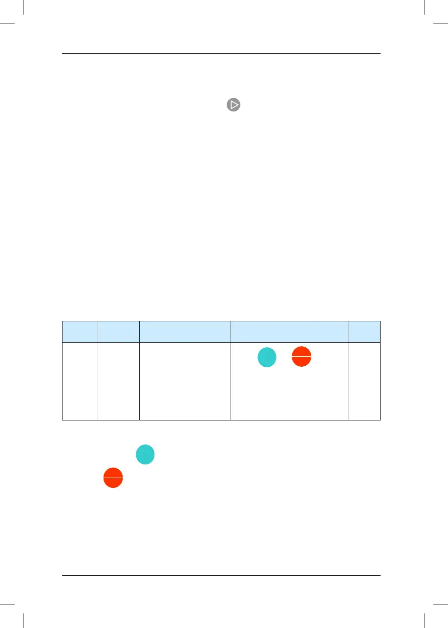
Function
Code
Parameter
Name
Setting Range Description Default
F0-02
Command
source
selection
0: Operation panel control
(indicator OFF)
1: Terminal control
(indicator ON)
2: Communication control
(indicator blinking)
Press
or
to start
or stop the AC drive.
A DI terminal needs to be dened
as the run/stop terminal.
The Modbus-RTU communication
protocol is used.
0
• 0: Operation panel control
After you press
, the AC drive starts running (the RUN indicator is ON). After you
press
when the AC drive is in running state, the AC drive stops running (the
RUN indicator is OFF).
• 1: Terminal control
This control mode is applicable to scenarios where the DIP switch or electromagnetic
button is used to start or stop the application system or scenarios where the dry contact
signal is used to start or stop the AC drive.
 Loading...
