EasyManuals Logo
Home>Intel>Server Board>S1200BTLRM

Intel S1200BTLRM Specification

Intel S1200BTLRM
153 pages
To Next Page IconTo Next Page
To Previous Page IconTo Previous Page
Page #105 background imageLoading...
Page #105 background image
Intel® Server Board S1200BT TPS Connector/Header Locations and Pin-outs
Revision 1.0
Intel order number G13326-003
93
Pin
Name
Pin
Name
17
GND
18
RXD_0
19
GND
20
RXD_1
21
GND
22
RXD_2
23
GND
24
RXD_3
25
GND
26
TX_CLK
27
GND
28
RX_CLK
29
GND
30
PRESENT#
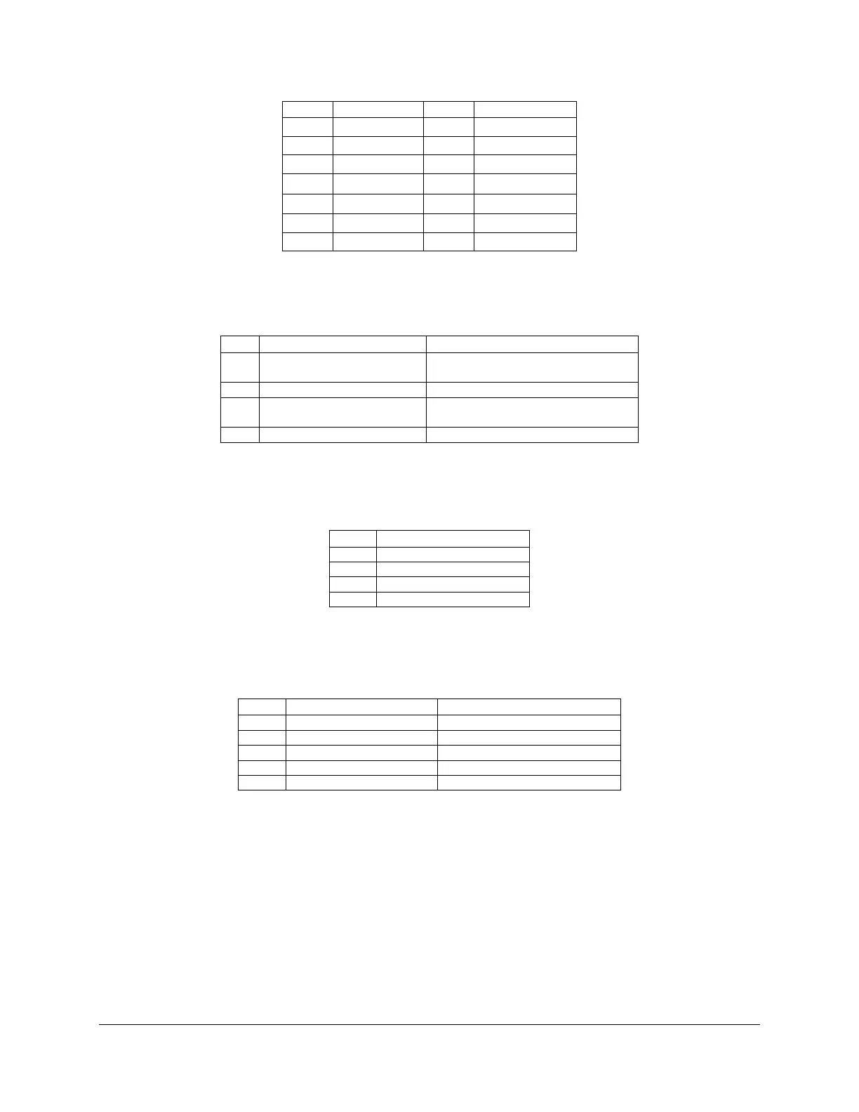
7.3.2 LPC/IPMB Header
Table 23. LPC/IPMB Header Pin-out (J1H5)
Pin
Signal Name
Description
1
SMB_IPMB_5VSB_DAT
Integrated BMC IMB 5V standby
data line
2
GND
Ground
3
SMB_IPMB_5VSB_CLK
Integrated BMC IMB 5V standby
clock line
4
P5V_STBY
+5 V standby power
7.3.3 HSBP Header
Table 24. HSBP Header Pin-out (J1J2)
Pin
Signal Name
1
SMB_HSBP_5V_DAT
2
GND
3
SMB_HSBP_5V_CLK
4
FM_HSBP_ADD_C2
7.3.4 SGPIO Header
Table 25. SGPIO Header Pin-out (J1J3 on S1200BTL and J2J2 on S1200BTS)
Pin
Signal Name
Description
1
SGPIO_CLOCK
SGPIO Clock Signal
2
SGPIO_LOAD
SGPIO Load Signal
3
GND
4
SGPIO_DATAOUT0
SGPIO Data Out
5
SGPIO_DATAOUT1
SGPIO Data In
7.4 Front Control Panel Connector
The server board provides a 24-pin SSI front panel connector (J1C1) for use with Intel
®
and
third-party chassis. The following table provides the pin-out for this connector.
Table 26. Front Panel SSI Standard 24-pin Connector Pin-out (J1C1 on S1200BTL or J1C2 on
S1200BTS)

Table of Contents

Other manuals for Intel S1200BTLRM

Questions and Answers:

Question and Answer IconNeed help?

Do you have a question about the Intel S1200BTLRM and is the answer not in the manual?

Intel S1200BTLRM Specifications

General IconGeneral
BrandIntel
ModelS1200BTLRM
CategoryServer Board
LanguageEnglish

Related product manuals