EasyManuals Logo
Home>Intel>Server Board>S1200BTLRM

Intel S1200BTLRM Specification

Intel S1200BTLRM
153 pages
To Next Page IconTo Next Page
To Previous Page IconTo Previous Page
Page #109 background imageLoading...
Page #109 background image
Intel® Server Board S1200BT TPS Connector/Header Locations and Pin-outs
Revision 1.0
Intel order number G13326-003
97
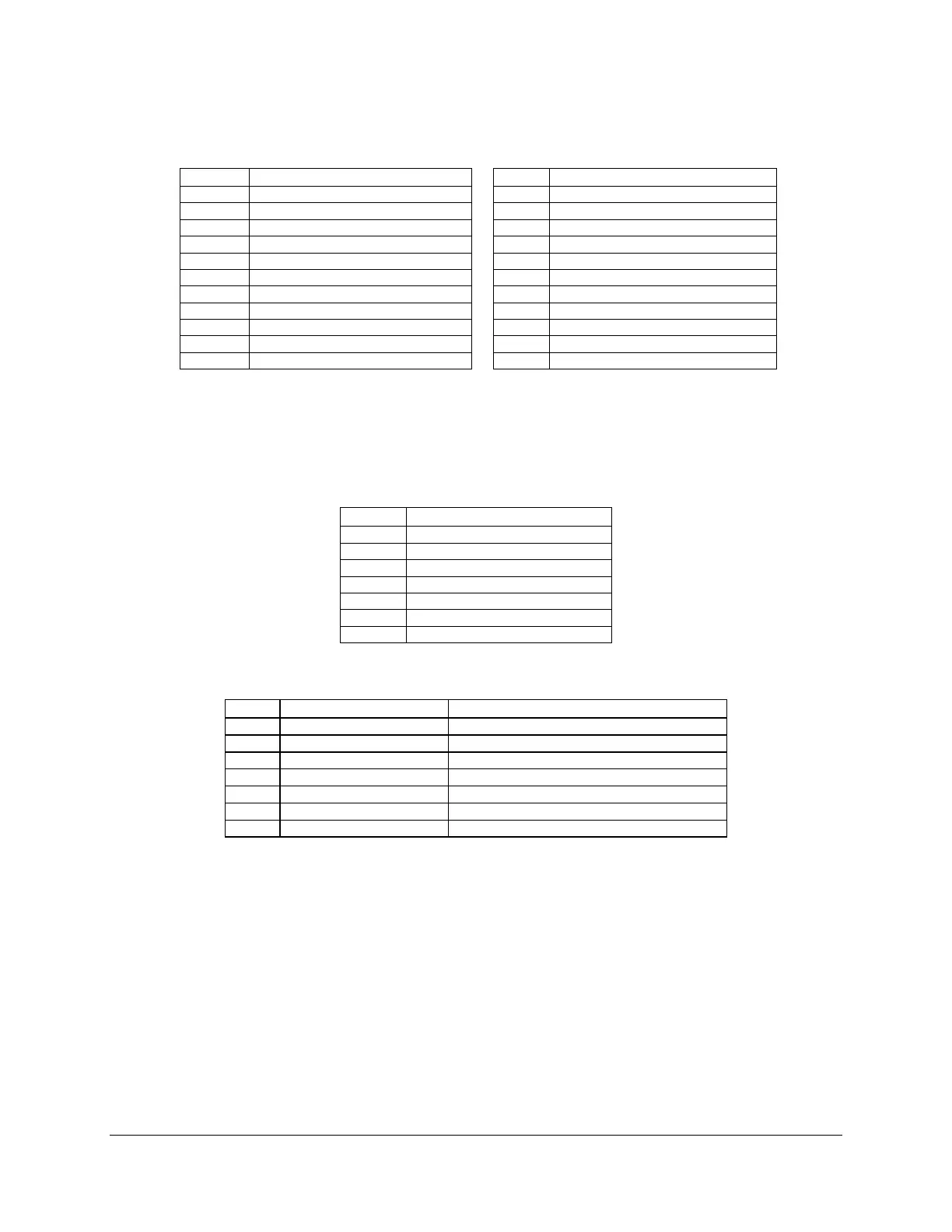
Table 30. RJ-45 10/100/1000 NIC Connector Pin-out (J6A1)
Pin
Signal Name
Pin
Signal Name
1
P5V_USB_PWR75
2
USB_PCH_11_FB_DN
3
USB_PCH_11_FB_DP
4
GND
5
P5V_USB_PWR75
6
USB_PCH_10_FB_DN
7
USB_PCH_10_FB_DP
8
GND
9
P1V8_PHY_VCT_R
10
NIC1_MDIP<0>
11
NIC1_MDIN<0>
12
NIC1_MDIP<1>
13
NIC1_MDIN<1>
14
NIC2_MDIP<2>
15
NIC1_MDIN<2>
16
NIC2_MDIP<3>
17
NIC1_MDIN<3>
18
GND
19
LED_NIC1_LINK_ACT_0_R
20
P3V3_AUX
21
LED_NIC1_2
22
LED_NIC1_LINK1000_1
7.5.3 SATA
The sever board provides up to two 6Gb/s SATA connectors and four 3Gb/s SATA connectors.
The pin configuration for each connector is identical and defined in the following table:
Table 31. 6Gb/s SATA Connector Pin-Out
Pin
Signal Name
1
GND
2
SATA_TX_P
3
SATA_TX_N
4
GND
5
SATA_RX_N
6
SATA_RX_P
7
GND
Table 32. 3Gb/s SATA Connector Pin-out
Pin
Signal Name
Description
1
GND
Ground
2
SATA/SAS_TX_P_C
Positive side of transmit differential pair
3
SATA/SAS_TX_N_C
Negative side of transmit differential pair
4
GND
Ground
5
SATA/SAS_RX_N_C
Negative side of receive differential pair
6
SATA/SAS_RX_P_C
Positive side of receive differential pair
7
GND
Ground
7.5.4 SAS Connectors
The Intel
®
Server Board S1200BTL provides one SAS connector.
The pin configuration is identical and defined in the following table:

Table of Contents

Other manuals for Intel S1200BTLRM

Questions and Answers:

Question and Answer IconNeed help?

Do you have a question about the Intel S1200BTLRM and is the answer not in the manual?

Intel S1200BTLRM Specifications

General IconGeneral
BrandIntel
ModelS1200BTLRM
CategoryServer Board
LanguageEnglish

Related product manuals