13 Mounting
Chapter 2:
Mounting
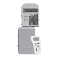
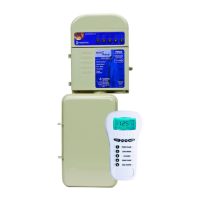
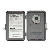
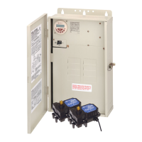
Mounting the PE653RC System
Follow this procedure to mount the MultiWave enclosure and PE653 receiver.
1. Select a location to mount the receiver that is near the pool/spa equipment; at least 3m
(in Canada) or 5 ft (in USA) from the inside wall of the pool, spa, or pond, unless separated
from the body of water by a fence, wall, or other permanent barrier that will make the unit
inaccessible to persons in the water. NOTE: The receiver must be mounted in a vertical
(upright) position on top of the enclosure.
2. Select the knockouts to be used and insert a athead screwdriver into the slot and carefully
punch the 1/2" knockout loose and remove the slug.
NOTE: If a 3/4" knockout is required, remove the outer ring with pliers after removing the
1/2" knockout. Smooth the edge with a le if required.
NOTE: If a low voltage circuit or a heater control circuit is to be used, remove the low
voltage knockout from the PE653 enclosure.
3. Install conduit hub to knockout rated for outdoor locations, raintight, or wet locations that
complies with the requirements in UL 514B (standard for tting for conduit and outlet box).
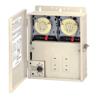
4. Place the metal enclosure in the desired mounting location and mark the three mounting
holes. Install the top screw rst and then hang the enclosure by the keyhole. Then install the
bottom screws, tightening all screws for a secure mounting.
5. Install conduit as needed to comply with national and local electrical and safety codes.
6. Bond the enclosure in accordance with your state and local codes. Where required, connect a
No. 8 AWG solid copper wire to the enclosure with a Bonding Lug (part number 156T11047A).
Connect the bonding wire to an approved earth ground.
7. Identify and install all wires necessary to complete the installation. Allow a length of
approximately 18" (46 cm) of each wire at the metal enclosure for required connections of
junctions.
8. Connect wiring for circuits as required. Refer to the diagrams in Chapter 3 and Chapter 4 for
wiring suggestions for specic equipment combinations. All splices and wire nut connections
should be in the metal enclosure, not in the PE653 enclosure.
9. Check and tighten all connections and circuits.
10. Apply power.
 Loading...