www.intermatic.com
48
MultiWave Control System Installation Guide
Sensors
Installing the Water Temperature Sensor
1. Make sure power is disconnected to the receiver.
2. Find a location to install the water temperature
sensor. The sensor must be installed after the lter
and before the input for the heater.
3. Drill a 3/8 inch hole in the pipe between the
lter pump and the lter.
4. Install the water temperature sensor probe into the
hole in the pipe and secure with a hose clamp. Make
sure the probe o-ring is in place.
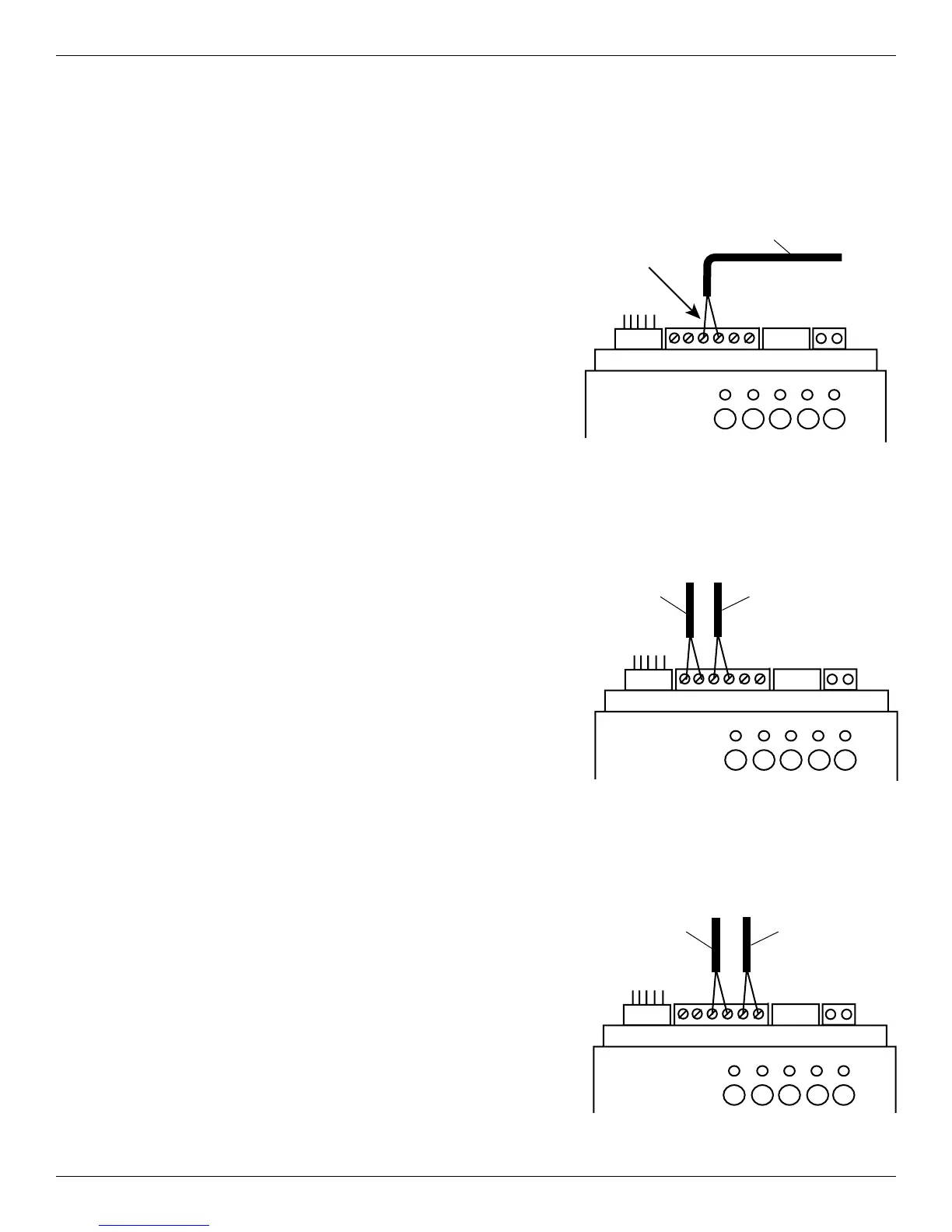
5. Run the sensor wires to the receiver and insert both
wires into the middle terminals on the 6-pin terminal
block at the top of the receiver.
See Figure 7-5.
Installing the Freeze (Air Temperature)
Sensor
1. Make sure power is disconnected to the receiver.
2. Install the sensor onto a piece of conduit.
NOTE: Be sure to mount the sensor in a location that
enables it to accurately measure the air temperature.
3. Run the sensor cable to the receiver.
4. Cut the connector off the cable with a wire cutter.
5. Strip the ends of the exposed cable wires and then
insert the wires into the terminals to the
left of the water temperature sensor wires.
See Figure 7-6.
NOTE: You do not have to observe polarity when
connecting the cable wires.
Installing the Solar (Air Temperature) Sensor
1. Make sure power is disconnected to the receiver.
2. Install the sensor onto a piece of conduit.
NOTE: Be sure to mount the sensor in a location that
enables it to accurately measure the air temperature
near the solar collector.
3. Run the sensor cable to the receiver.
4. Cut the connector off the cable with a wire cutter.
5. Strip the ends of the exposed cable wires and then
insert the wires into the terminals to the
right of the water temperature sensor wires.
See Figure 7-7.
NOTE: You do not have to observe polarity when
connecting the cable wires.
1 2 3 4 5
Figure 7-5. Connecting water temperature
sensor cable wiring.
Middle
Terminals on
6-pin Terminal
block
Water
Temperature
Sensor Cable
1 2 3 4 5
Figure 7-6. Connecting freeze (air temperature)
sensor cable wiring.
Freeze
(AirTemperature)
Sensor Cable
Water
Temperature
Sensor Cable
1 2 3 4 5
Figure 7-7. Connecting solar (air temperature)
sensor cable wiring.
Solar
(AirTemperature)
Sensor Cable
Water
Temperature
Sensor Cable
 Loading...