www.intermatic.com
16
MultiWave Control System Installation Guide
Ratings
Chapter 3:
Installing — Ratings, 120V/240V Wiring, Power In/Out
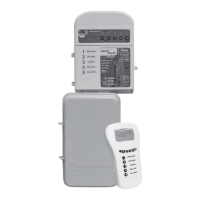
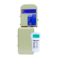
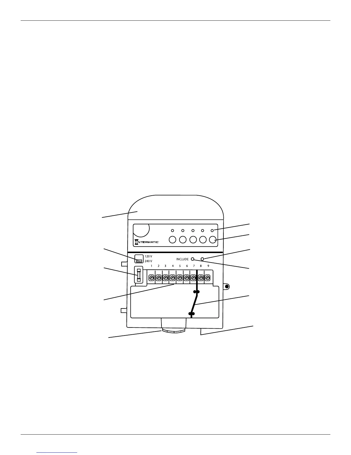
Figure 3-1. PE653 Receiver.
Low Voltage Divider
(can be removed)
Load ON Indicator
(Green LEDs)
Circuit ON/OFF Switches
Include/Exclude Switch
AC Power & Status
Indicator (Red)
Low Voltage Knockout
Antenna Section
Threaded Conduit
Connection Bushing and Hub
120/240 VAC Selector
Switch
Fuse (250 VAC - 0.1 A)
Wiring Terminals
Controller Power In:
•
120/240 VAC, 50/60 Hz, 5 W max.
Contact Ratings:
Load 1
•
120/240 VAC
•
20 A Resistive
•
17 Full Load A, 80 Lock Rotor A
•
5A Tungsten
Loads 2-5
•
120/240 VAC
•
15 A Resistive
•
10 Full Load A, 60 Lock Rotor A
•
5A Tungsten
IMPORTANT: The installer must fill out the MultiWave Pool & Spa Control System Worksheet
for Programming at the back of this guide so that the controller can be programmed.
 Loading...