www.intermatic.com
24
MultiWave Control System Installation Guide
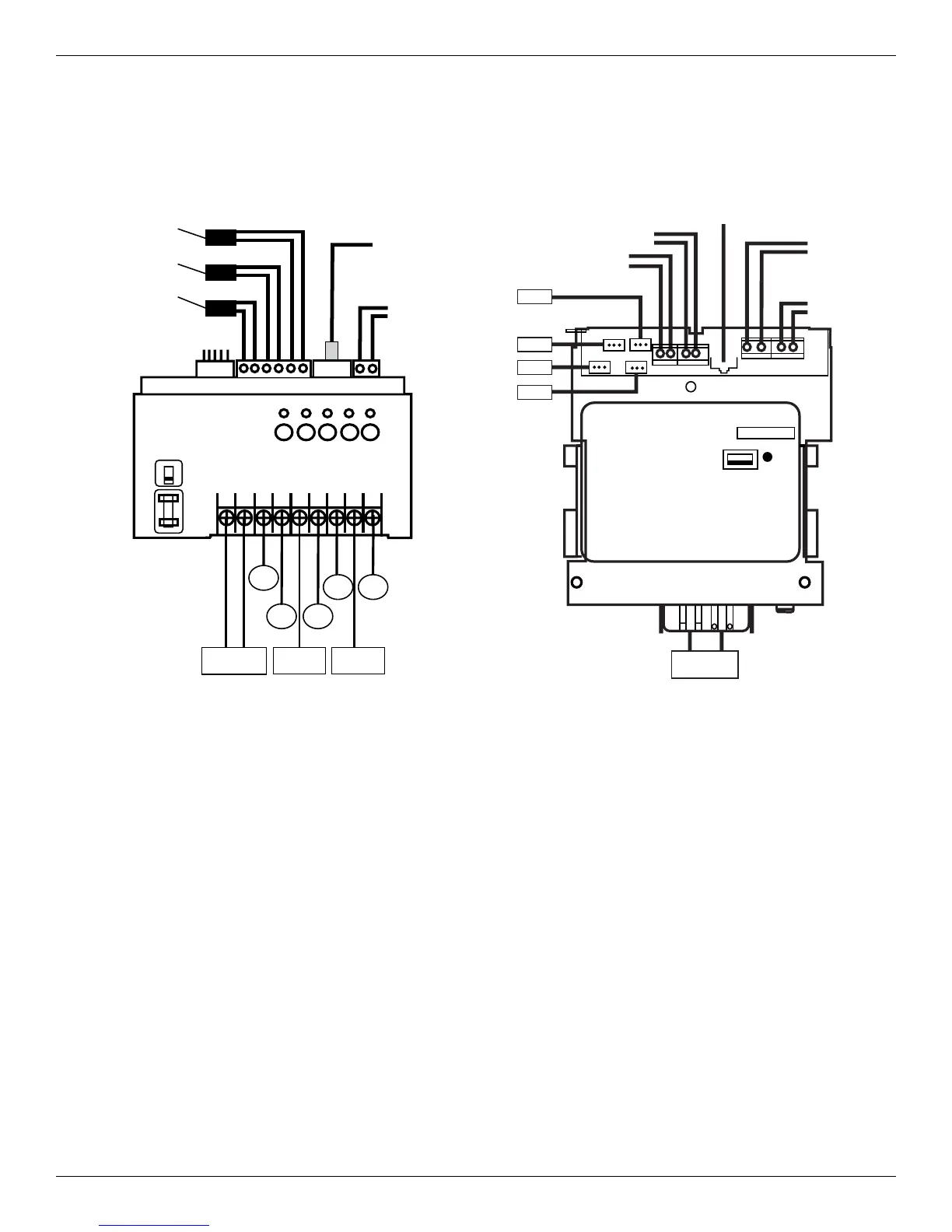
1-Speed Pump Terminal/Circuit Connections for PE653RC with
P5043ME
123 4 5 6 7 8 9
1 2 3 4 5
Water
Temperature
Sensor
Circuit
1
Circuit
2
Circuit
3
Circuit
4
Circuit
5
Power In
120or240 VAC
L1 120
VACWire
L2
120V
240V
Solar/Air
Temperature
Sensor
Freeze/Air
Temperature
Sensor
Antenna
Extender
(CAT5)
Pentair VSP and/or SCG
AND Expansion Module
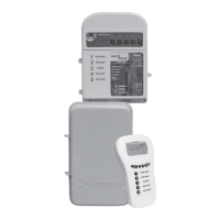
PE653 Receiver
Terminals 1, 2, 5 and 8 – Power In
Terminal 3, Circuit 1 – 120/240 VAC 1-Speed Pump*
Terminal 4, Circuit 2 – 120/240 VAC Auxiliary
Terminal 6, Circuit 3 – 120/240 VAC Booster
(Cleaner) Pump*
Terminal 7, Circuit 4 – 120/240 VAC Blower*
Terminal 9, Circuit 5 – 120 VAC Light with GFCI
* To break both lines, use relay kit PE21RLY.
Request document 158--01559.
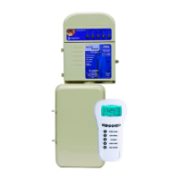
P5043ME Expansion Module
Power In
NOTE: Expansion module hookups are shown on
page 21, page 37 and page 39.
Act 2
Act 1
Act 3
Act 4
Power In
240 VAC
Heater #1
Heater #2
Remote
Switch
Comm Cable
to Receiver
Other VSP
(CAT5)
Figure 4-3. PE653 Receiver Connections.
Figure 4-4. P5043ME Expansion Module Hookups.

 Loading...