EasyManua.ls Logo

ITech IT-M3412 User Manual

ITech IT-M3412
153 pages
To Next Page IconTo Next Page
To Previous Page IconTo Previous Page
Page #56 background image
Output Function
The heavy solid line illustrates the locus of possible operating points as a
function of output. As shown by the horizontal portion of the line, the output
voltage remains regulated at its programmed setting as long as the load current
remains within the positive or negative current limit setting. A CV status flag
indicates that the output voltage is being regulated and the output current is
within its limit settings.
Note that when the output current reaches either the positive or negative
current limit, the unit no longer operates in constant voltage mode and the
output voltage is no longer held constant. Instead, the unit will now regulate the
output current at its current limit setting.
As shown by the vertical portions of the shaded quadrants, the output voltage
may continue to increase in the positive direction or decrease in the negative
direction as current is forced into or pulled out of the unit. When the output
voltage exceeds the over-voltage protection setting, the output will shut down.
CC priority mode:
Copyright © Itech Electronic Co., Ltd.
45

Table of Contents

Question and Answer IconNeed help?

Do you have a question about the ITech IT-M3412 and is the answer not in the manual?

ITech IT-M3412 Specifications

General IconGeneral
ModelIT-M3412
Voltage Resolution1mV
Current Resolution0.1mA
Current Accuracy0.1% + 5mA
Programming Response Time< 50ms
Display4.3-inch TFT LCD
Operating Temperature0°C to 40°C
Storage Temperature-20°C to 70°C
CategoryPower Supply
Output Current0 ~ 10A
Voltage Accuracy0.05% + 5mV
Ripple and Noise (CC)≤ 3mArms
InterfaceUSB, LAN, RS232, GPIB

Summary

Introduction and Safety

Safety Notices and Symbols

Explains safety symbols (Caution, Warning, Note) and general safety guidelines.

Warranty and Compliance

Details product warranty terms, limitations, and compliance information.

Setup and Basic Operations

Quick Reference and Installation

Introduces basic operations, setup, and connecting interfaces.

Communication Interfaces

Guides on installing and connecting various communication interface cards.

System Settings

Covers key lock, save/recall, mode switching, beeper, power-on state, and communication settings.

Core Functions

Getting Started and Output Control

Instructions for initial power-on, basic controls, and output parameter configuration.

Advanced Functions

Covers List function, battery tests, and battery emulation.

Protection Settings

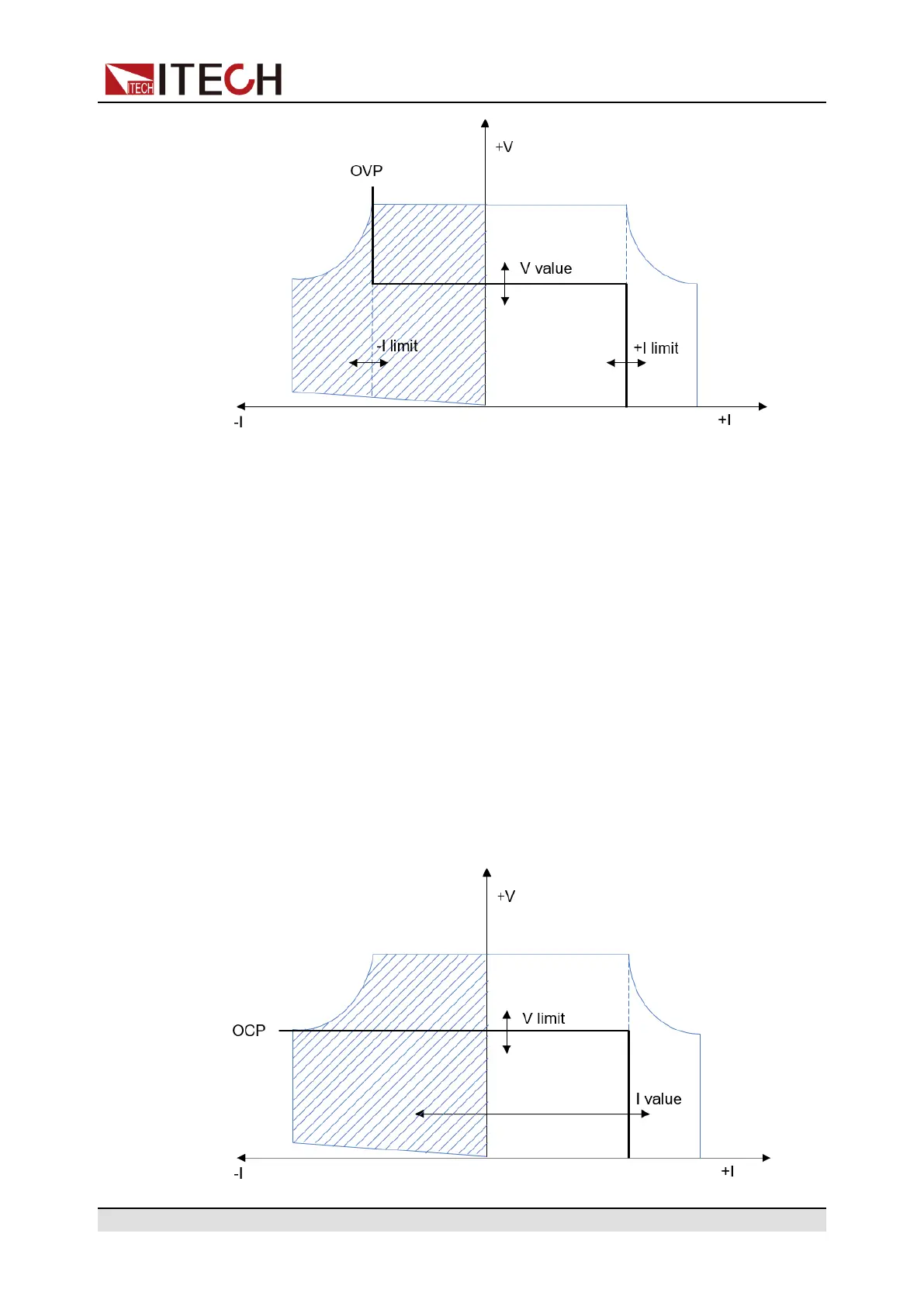
Configuring over-voltage, over-current, and other protective measures.

Advanced System Operations

Multi-Machine and Parallel Operation

Connecting and controlling multiple instruments for enhanced capabilities.

Maintenance, Specifications, and Appendix

Routine Maintenance and Support

Instrument self-test, cleaning, troubleshooting, and contact information.

Technical Specifications

Detailed technical parameters for various IT-M series models.

Appendix Information

Includes test cable specifications and contact details.

Related product manuals