Quick Reference
9. Communication interface of inner ring optical fiber (F-TX and F-RX)
This interface is used for the parallel connection between the master (with
operation panel) and the slaves (without operation panel) for realizing
communication of units in parallel.
10.Communication interface of outer ring optical fiber (TX and RX)
This interface is used for the parallel connection between the masters
(with operation panel) for the communication of units in parallel.
11.AC power input terminals (L1, L2, L3, and PE)
12.Chassis ground terminal
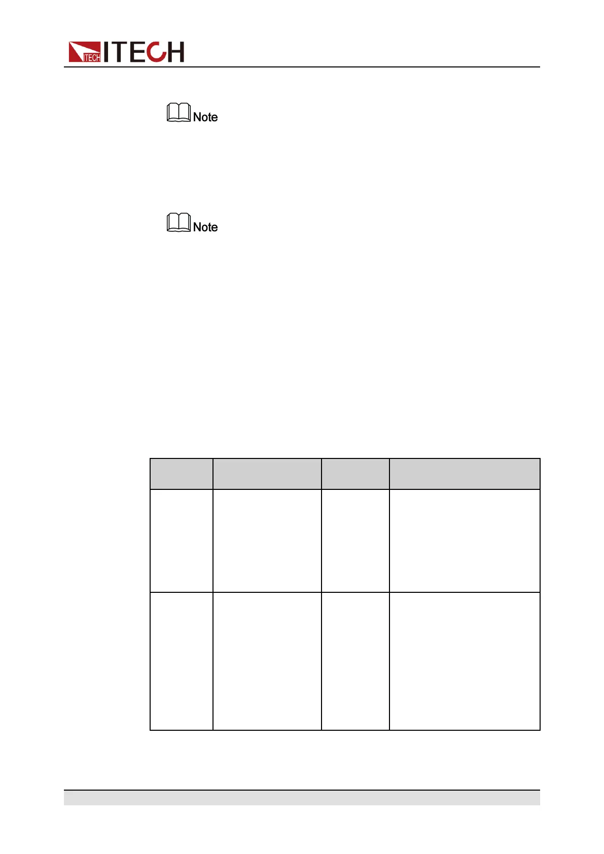
1.6 VFD Indicator Lamps Description
The IT6000B series Regenerative Power System VFD indicator lamps descrip-
tion is as follows:
Table 1–1 VFD Indicator Lamps Description
Flag Function
Description
Flag Function Description
OFF Source mode: The
output of the power
supply is turned off.
Load mode: The in-
put of the load is
turned off.
Sense Sense function of the power
system is enabled.
CV Source mode: The
power supply is in a
state of constant
voltage output.
Load mode: The
load is in a state of
constant voltage
input.
Rear Analog function begin to
work.
Copyright © Itech Electronic Co., Ltd.
9
 Loading...
