Basic Operation
Revert to Single Mode
1. Set each of the three instruments to single mode.
a. Press the composite keys [Shift]+[P-set] (System) on the front panel to
enter the system menu.
b. Set the Parallel to Single.
For details, see Configure the Menu Item.
2. Power off the three instruments and turn off the main switch of the AC distri-
bution box.
3. Remove the cables connection of the System Bus and DC output terminals
between three units.
4. Power on the three instruments separately.
After the instrument is restarted, the VFD shows that the instrument is work-
ing in single mode.
5.11 Digital I/O Function (Digital Port)
The IT6000D series power supply supports digital I/O function. The user can
realize logic control over high and low level input or output by related configura-
tions in the system menu, namely general digital signal I/O function. In addition
to general digital I/O functions, this series can be customized to meet different
special needs through different pin wirings. For example, you can connect a pin
to an external instrument, and set a fixed pulse or level signal for the external in-
strument. Once the external instrument fails, output this pulse or level signal.
After the instrument identifies this signal, it controls whether the power supply
output is reduced to 0 or whether the [On/Off] is switched off based on related
settings.
The rear panel of the instrument has a green 8-pin terminal (For position, see
1.5 Rear Panel Introduction). The terminal is a wiring terminal with digital I/O
function. These pins are bi-directional I/O interfaces. For hardware index infor-
mation, see Table 5–2 Hardware parameters of the I/O interface. The pins sup-
port the input or output of pulse and high and low level. Different pins can
achieve different functions.
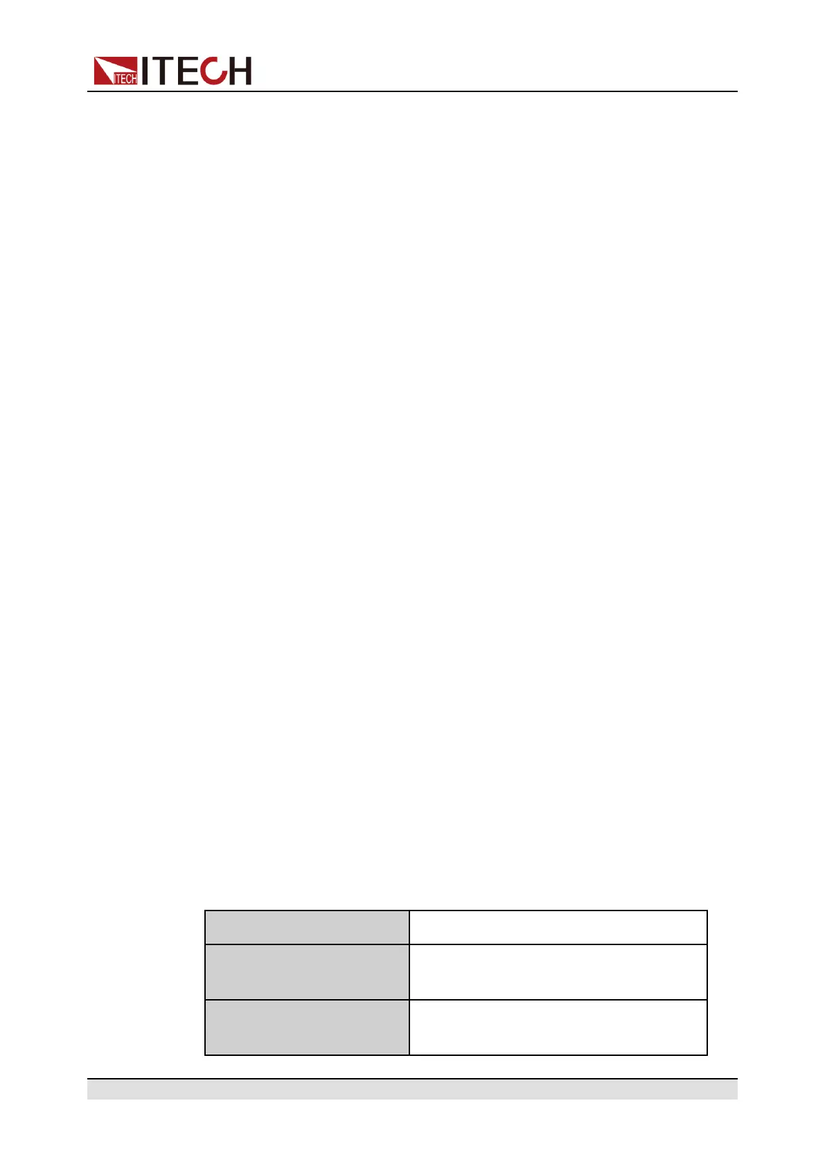
Table 5–2 Hardware parameters of the I/O interface
Input voltage range -5V to +15V
Maximum low level output
voltage
0.65V
Maximum low level input
voltage
0.8V
Copyright © Itech Electronic Co., Ltd.
94

 Loading...