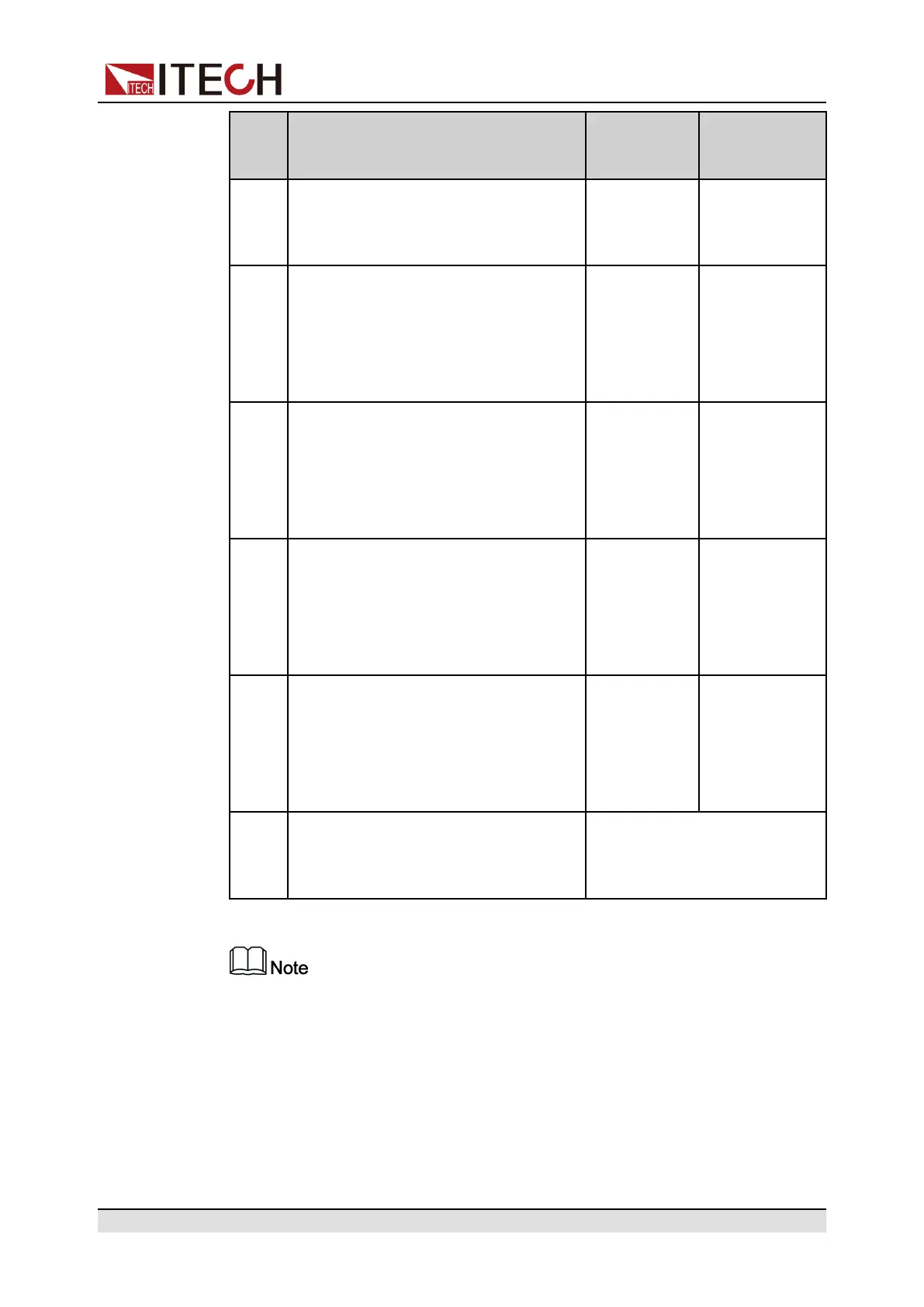
Basic Operation
Pin Description Properties
(Default
function)
Properties
(General I/O
function)
Status, Not-Invert menu item. For
parameter introduction, see 5.11.3
IO–3. Off-Status, Not-Invert.
4 Corresponds to the function set in the
System→Digital Port→IO–4. Ext-
Trig, Not-Invert menu item. For pa-
rameter introduction, see 5.11.4 IO–
4. Ext-Trig, Not-Invert.
Pulse signal Level or PWM
signal
5 Corresponds to the function set in the
System→Digital Port→IO–5. INH-
Living, Not-Invert menu item. For
parameter introduction, see 5.11.5
IO–5. INH-Living, Not-Invert.
Pulse signal Level or PWM
signal
6 Corresponds to the function set in the
System→Digital Port→IO–6. Sync-
On, Not-Invert menu item. For pa-
rameter introduction, see 5.11.6 IO–
6. Sync-On, Not-Invert.
Pulse signal Level or PWM
signal
7 Corresponds to the function set in the
System→Digital Port→IO–7. Sync-
Off, Not-Invert menu item. For pa-
rameter introduction, see 5.11.7 IO–
7. Sync-Off, Not-Invert.
Pulse signal Level or PWM
signal
GND Ground terminal, that is, the negative
terminal corresponding to each of the
above 7 pins.
Level signal
In this chapter, all the pulse signals involved in the digital I/O function are
switched from high level to low level.
Taking pin 1 as an example, IO–1. Ps-Clear, Not-Invert contains three function
options, the first option Ps-Clear is the default function, and this function is also
a special custom function unique to this pin (the seven pins each have a differ-
ent custom function). The second and third options (Input and Output) are the
general digital I/O function, and the parameter settings and functions of the sev-
en pins are the same.
Copyright © Itech Electronic Co., Ltd.
96

 Loading...