Function and Features
Copyright ©ITECH Electronic Co., Ltd. 28
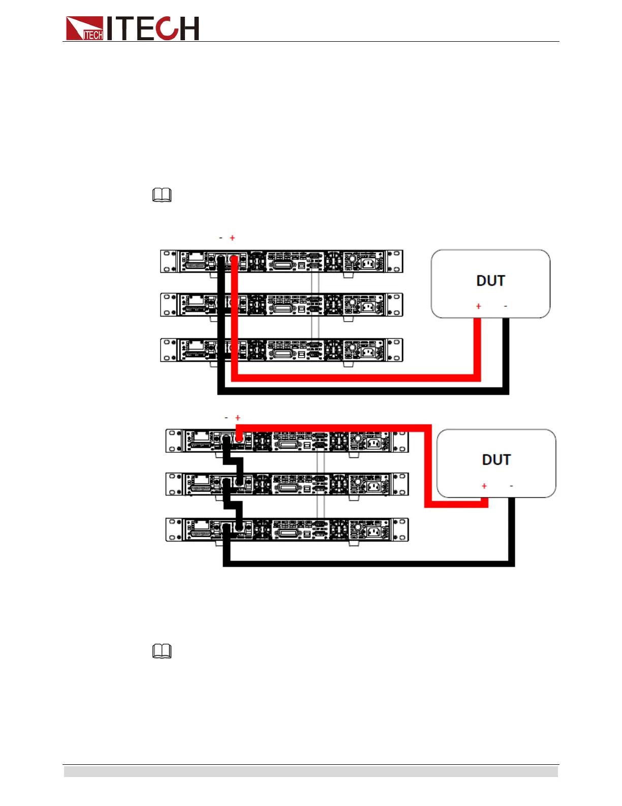
Connect each power supplies’ positive (+) terminals together. Do the same for the negative
(-) terminals.
For series connection:
Connect one power supply’s positive (+) terminal to the negative (-) terminal of another.
Do the same for all the power supplies.
Then, connect all of the power supplies’ Pin 1 of the RS-485 interface together. Do the
same for Pin 5.
Below illustrates the connection diagram for parallel connection.
Note
Be sure to use wires that can support the amount of output current that you want to output from the power
supplies. Refer to “2.2 Output Connetction” for details.
Master/Slave Setup
Only one power supply has to be configured as a Master. The rest must be configured as
Slave. Up to 3 units can be configured in total.
Note
Configure Slave power supplies FIRST, and configure the Master power supply LAST. For remote or
front board operation, only control the Master power supply.
Master/Slave Configuration
After physically connecting the power supplies for parallel or series operation, power ON
the power supplies and follow the steps below to configure a power supply as a master or
 Loading...


