45
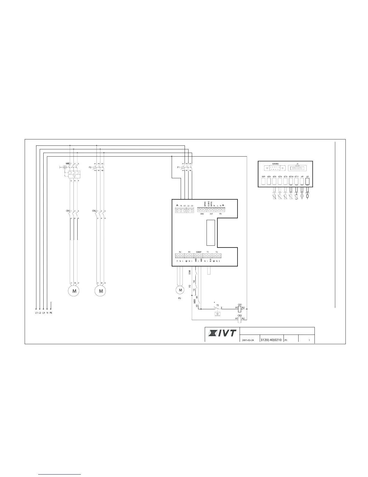
Terminal card
* In models D25-D40
Incoming supply
3 x400V + N + PE
G3 (P3) Heat transfer
fluid pump
MB 1: Motor cutout compressor
CK 1: Contactor compressor
CK 2: Contactor, heat transfer fluid pump
F 1: Circuit-breaker heat pump
F2: Circuit breaker, heat transfer fluid pump
TS: Thermal protection (not D20)
SSM: Motor cutout heat transfer fluid pump
Compressor
Circuit diagram, Greenline D20-D40
Sensor board
Internal couplings
Low pressure switch
Pressure switch high
HTF (coll) out
HTF (coll) in
Heat trfr fld in
Heat trfr fld out
Compressor
CIRCUIT DIAGRAM
IVT GREENLINE D20-D40
DATE DRAWING NUMBER DRAWN BY PAGE
 Loading...