49
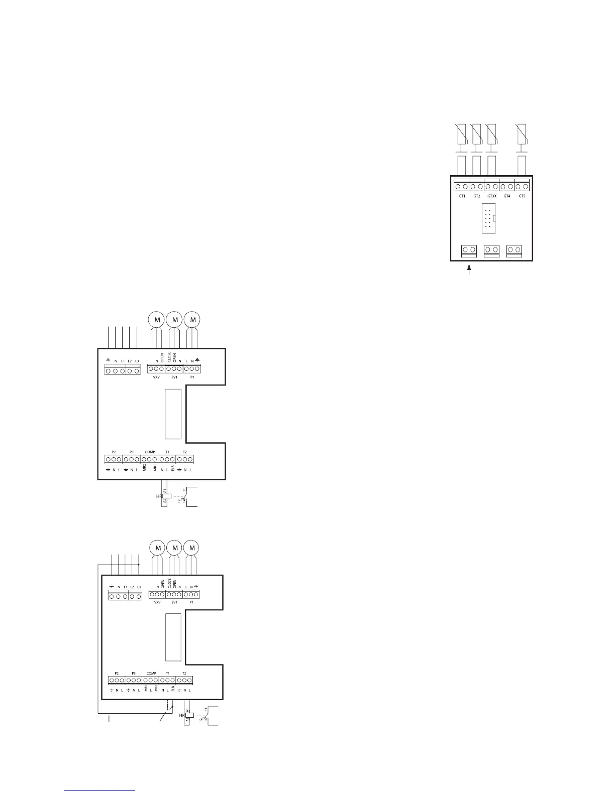
External connections in the D series
• Power supply: Connect to terminals L1, L2, L3, N and PE. Alarm triggers if
phases connected wrongly.
• 3-way valve: Connected if the heat pump is to produce hot water. Con-
nected to terminals VXV.
• Mixing valve for oil-fired boiler: If a mixing valve is required for the oil-
fired boiler then it is connected to terminals SV1.
• G1 (P1), external main pump in the heating system: Must always be
connected. Connected to terminals P1.
• Return sensor radiator T1 (GT1): Must always be connected. Connected
to terminals GT1.
• Outdoor sensor T2 (GT2): Must always be connected. Connected to
terminals GT2.
• Hot water sensor T3 (GT3): Connected if the heat pump is to produce hot
water. Connected to terminals GT3 X
• Room sensor T5 (GT5): Connected if room sensor influence required.
Connected to terminals GT5. If room sensor alarm is required it is connected
to terminals ALARM LED.
Cut the cable to the oil-
fired boiler/electric boiler
and connect to relay
terminals 11 and 14.
Wiring to the
electric heater,
(starting) is
connected to
relay terminals
11 and 14.
TERMINAL
CARD
TERMINAL
CARD
TERMINAL
CARD
Return radiator
Out
Hot water
Room
Alarm lamp,
room sensor.
INC. POWER SUPPLY
3X400VAC+N+PE
P1
ALARM
LED
GENERAL
ALARM EXT
Connection of additional heat to oil and electric boiler,
operating mode B
When additional heat is from an oil-fired or electric boiler with
a mixing valve the wiring to the burner or contactor is con-
nected to terminals N and L on contact T1 via a help relay
HR. L1 provides 230Vac.
If the electric boiler has an inlet for telecontrol it is connected
to the help relay.
Connecting additional heat to electric heater, operating
modes A and C
If the additional heat is an electric heater it is connected in the
following way: Remove the strap between L and ELB on
contact T1. Fit a new strap between terminal L3 and ELB on
contact T1. Fit the coil on help relay HR to N and L on
contact T2. The electric heater’s on/off is connected to the
help relay terminals 11 and 14. Concerns both contactors and
telecontrol function in the electric heater.
Connecting power is set at 2/3 in the 5.2 menu display
If the alarm function for the electric heater’s overheat protec-
tion is required the strap between L3 and ELB should not be
fitted and the strap between L and ELB is removed. Instead a
strap is fitted to ELB from the overheat protection, PLEASE
NOTE! Must be phase L3. (see circuit diagram E series)
New strap
Removed
3-WAY
VALVE
MIXING
VA L V E
INC. POWER SUPPLY
3X400VAC+N+PE
P1
3-WAY
VALVE
MIXING
VA L V E
 Loading...