48
Terminal card
Terminal
card
external
couplings
Return radiator
Out
Hot water
Mixing valve
Room
Mixing valve
P1
Alarm lamp, room sensor.
Alarm
led
General
alarm
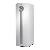
External connections in the E series
External connections that can be connected to the Greenline E series:
• Power supply: Connect to terminals L1, L2, L3, N and PE. Alarm triggers if phases connected
wrongly.
• Heating circuit with mixing valve: If a second heat curve with mixing valve is to be used, the
mixing valve is connected to terminals SV1.
• G1 (P1), external main pump in the heating system: Must always be connected. Connected to
terminals P1.
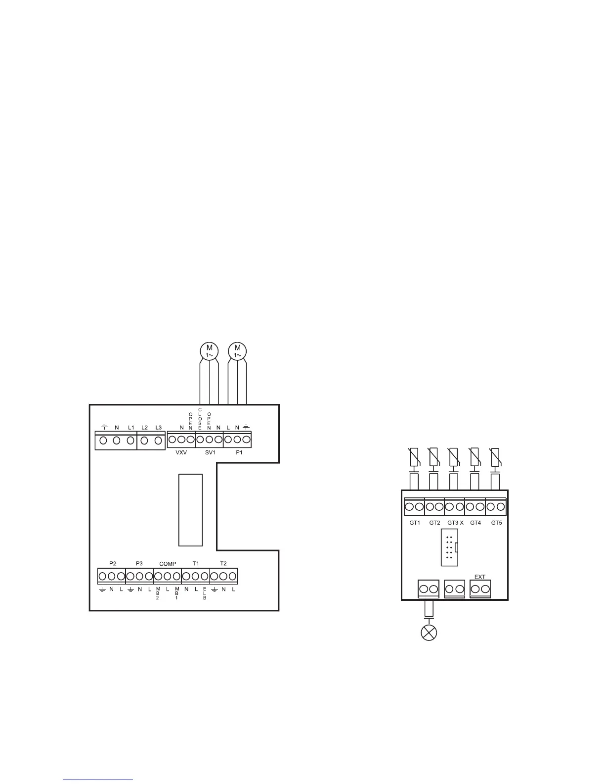
• Return sensor radiator T1 (GT1): Must always be connected. Connected to terminals GT1.
• Outdoor sensor T2 (GT2): Must always be connected. Connected to terminals GT2.
• Hot water sensor T3 (GT3): Connected if the heat pump is to produce hot water. Connected to
terminals GT3 X
• Mixing valve sensor T4 (GT4): Connected if the mixing valve for the second heat curve is used.
Connected to terminals GT4.
• Room sensor T5 (GT5): Connected if room sensor influence required. Connected to terminals
GT5. If room sensor alarm is required it is connected to terminals ALARM LED.
 Loading...