30
What the shipment includes
Standard components
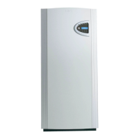
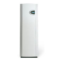
• heat pump unit with the necessary safety functions and electrical components
• factory mounted control unit Rego600. Rego600 can be used for simultaneous operation
together with an immersion heater or oil-fired or electric boiler with mixing valve.
• sensor radiator return, GT1 (packed separately).
• sensor hot water, GT3 (C series).
• sensor out, GT2 (packed separately).
• sensor, compressor, GT6.
• sensor heat transfer fluid out, GT8.
• sensor heat transfer fluid in, GT9.
• sensor heat transfer fluid (collector ) in, GT10.
• sensor heat transfer fluid (collector ) out, GT11.
• pump for heat transfer fluid and heat transfer circuits.
• built-in, flexible hoses on the heat transfer circuit.
• particle filter with shut off for heating and heat transfer fluid side (packed separately in C
and D series).
• expansion vessel and safety valve for heat transfer fluid circuit (packed separately).
• soundproof cover on compressor
Accessories
• sensor hot water, GT3 (D and E series).
• sensor flow duct mixing curve, GT4.
• room sensor, GT5.
General
Temperatures
Note that the heat pump can work to a maximum return temperature of around 48°C. Anything over
this and the heat pump stops for safety reasons. The maximum outgoing temperature from the heat
pump is around 55°C. A higher temperature can be achieved using an immersion heater.
Particle filter
The particle filter supplied must always be fitted in the input pipe of the hot side as close as possible
to the heat pump, and horizontally. The filter is mounted on the heat transfer side in the E series. The
filters is separately packed on the heat transfer fluid side.
Transportation
The heat pump must always be transported and stored upright and dry. The heat pump can be placed
on its back temporarily for moving into place of installation.
Positioning
Place the heat pump on a flat base and adjust the rubber feet until it is level. Avoid installing the heat
pump close to sensitive walls such as bedroom walls, since the pump produces a certain amount of
noise when running. The room must have a floor drain. Installation must comply with local construc-
tion regulations.
 Loading...
