52
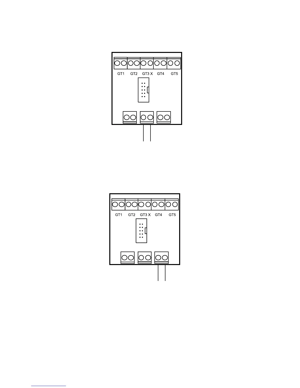
Connecting the general alarm
A general alarm is connected according to the sketch. The contact for the general alarm outlet is
floating. Max 24 volt, 100mA. The contact shuts at joint alarm.
Connecting the external input
The heat pump can be controlled by external control and be programmed in Rego600 for different
functions. Function choice is available in menu display 1.13 (remote control heating) and menu
display 5.7 (select external controls). The inlet is short-circuited to activate the function. You can
choose between more than one alternative in display 5.7 or 1.13.
Connecting the load monitor
A load guard can be connected to the external control input and in this way break the additional heat.
You programme function 3 in menu display 5.7. When the external inlet short circuits the additional
heat is broken. Heat pump operation is not affected. Connection as above. When this function is
chosen no other external controls can be used.
Terminal
card
internal
couplings
Terminal
card
internal
couplings
ALARM
LED
GENERAL
ALARM EXT
Inlet for external control of the heat pump.
The inlet is short-circuited to activate the
function.
NOTE: The contact must be floating.
Floating general alarm outlet.
Max 24 volt, 100mA.
Shuts at alarm.
ALARM
LED
GENERAL
ALARM
EXT
 Loading...


