37
Intermediate heat exchanger
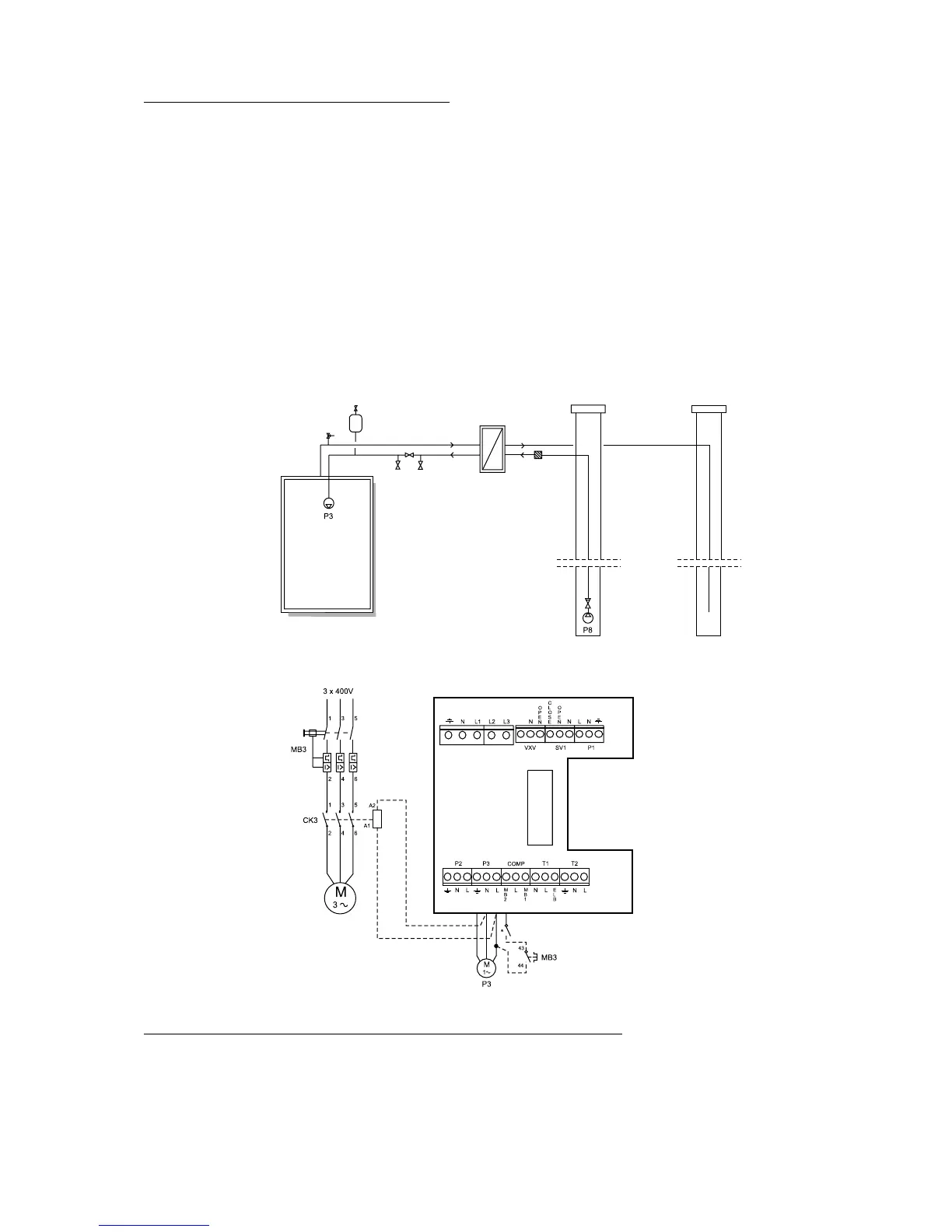
The flow in the exchanger must be
counterflow. The pipe from the well
is connected to the bottom of the
exchanger so that the flow goes
upwards.
Heat pump
Water source Recharge well
* Model 11 has a built-in motor
cutout in the pump.
Models 5-9 have a clamp mounted
between L and MB2.
Terminal card
Connecting to the heating system
General
Installation must be carried out by an authorised installer and must follow the current rules and recom-
mendations of IVT. The pipework must be flushed before the heat pump is connected to protect the
heat pump from contaminants.
Safety
valve
Filling unit
P8
Ground
water
water pump
Ground water system
Application:
Systems using ground water are equipped with an intermediate heat exchanger to eliminate the risk for
freezing. A pump with a non-return valve is placed in the bore hole that via a hose pumps the water to
the intermediate exchanger and then back to an injection well. The circuit to the heat pump is installed
in the normal way with a filling unit and safety valve. The circuit should contain around 29 volume
percent antifreeze (ethanol or ethylene glycol) which corresponds to around -15
o
C freezing point.
Electrical connections:
The ground water pump is connected to 3 x 400 volt with a motor cutout and a contactor. Power to
contactor CK3(230V) is fetched from terminals L and N (P3) in the heat pump. The auxiliary contact
for motor cutout MB3 is series connected with the MB2 alarm. In this way the ground water pump
starts and stops with the heat pump’s heat transfer fluid pump and during motor cutout MB3, the heat
pump stops and the heat transfer fluid pump alarm shows in the alarm display. NOTE: Single-phase
pumps should always be connected with a contactor. It should never be connected to the P3 outlet in
the heat pump.
Filter
Exp
 Loading...


