43
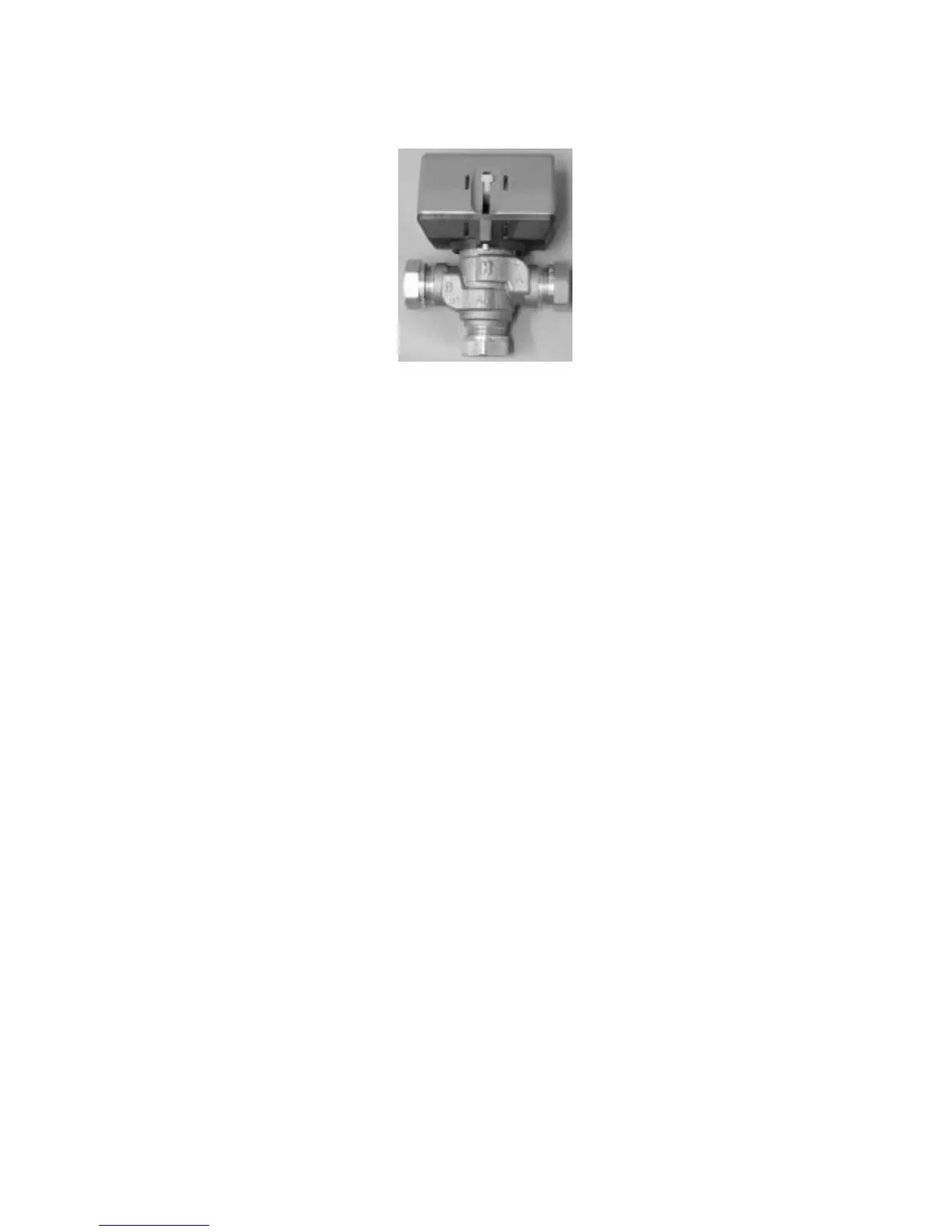
Connecting the 3-way valve
Connecting a Honeywell 3-way valve to hot water cylinder.
Filling the radiator system
Note that the radiator system must have its own expansion vessel. Open the valve between the cold
water system and the heating system in short bursts and then close it and note the pressure gauge
reading. When the system is full or the right pressure has been reached, vent the system and top it up if
necessary.
Filling of heat transfer fluid
The ground coil or well coils must be filled with a mixture of water and heat transfer fluid until a
freeze protection level of around -15°C is reached as shown in the following table.
Procedure when filling is (compare with the picture on the next page)
• Connect two one inch hoses to both filling valves 1 and 2. One hose has a submersiblepump
(min 6 m³/h) connected at the other end.
• Both hoses are placed in a barrel with a volume of at least 100 litres. The barrel is filled with a
mixture of antifreeze and water. As shown in the table on the next page. Always fill water before
antifreeze.
• Open valves 1 and 2, shut valve 3. Start the submersible pump (that is equipped with a particle fil-
ter!), and the system fills with liquid. Note that the first litres in the return pipe are usually
contaminated. So collect the first litres in a separate vessel.
• Open the expansion vessel valve until the vessel fills to around 2/3.
• When the level in the barrel has sunk to 25% the submergible pump stops and the barrel fills with the
antifreeze mixture.
• When the system is full and air is no longer coming from the return pipe the system is for a further 30
minute at least. You can start the heat pump’s heat transfer fluid pump to speed up the air venting. Go
into manual operation in display 5.3 and start pump P3.
• When venting is ready open valve 3, shut valve 2, and shortly after valve 1. Disconnect the hoses and
the transfer fluid side is ready for operation. Note that a little overpressure in the transfer fluid circuit
is beneficial.
Port B / to radiators.
Port A / to DHW cylinder
Port AB / from heat pump
 Loading...


