62
Technical information
Important points to check
During the first period after commissioning you should pay special attention to the pressure levels in
the heating system and heat transfer circuit. It might need filling up.
The factory setting of the motor cutout is based on a value under the hot water pressure and stable
voltage. Because of the various voltages in the electric network the recommended settings are not
always suitable and can therefore need adjusting from time to time. This is best achieved using a clip-
on ammeter during hot water operation.
For the heat pump to perform at its best, it is important to check the flow on the hot and cold side of
the heat pump. Usually, the heat transfer fluid pumps each have a speed selector switch. These must be
set correctly for the pressure drop in the systems. A recommended temperature difference over the heat
pump on the cold side is between 2-3°C and on the hot side between 7-10°C. The nominal flows
specified in Technical Specifications give a difference of 3°C to 7°C at operating mode 0/45°C. You
can check this with the help of the sensor temperatures in line three of the control panel.
It is also important that the flow in the radiator system exceeds the flow across the heat pump. If this is
not the case, the heat pump flow goes back via the bypass to the heat pump return, which may case the
heat pump to trip for high return temperature. The flow through the radiator system must be high
enough to ensure that the entiresurface of the radiators is kept hot. This maximises the heat-radiating
surface and so keeps down the flow temperature from the heat pump.
After testing, vent the system again and top up with cold water if necessary.
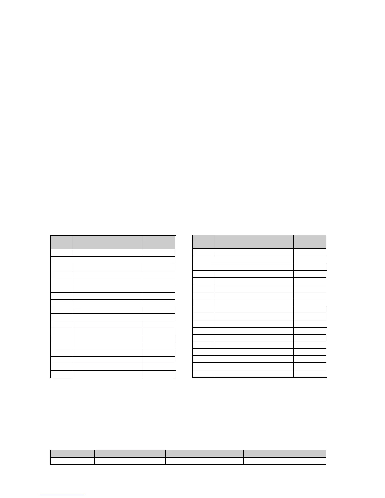
Table of factory settings
The table shows the factory settings of all the settings that can be changed by the installer.
P2.3 Setting of DHW temp. 45°
P2.4 Setting of DHW hysteresis 5°
P4.1 Clock setting HP not active
P4.1.1 Setting level HP 0°
P4.2 Clock sett. add. heat not active
P4.3 Clock setting DHW not active
P5.1 Select operating case A
P5.2 Conn. cap. electric add. heat. 2/3
P5.4 Only add. heat Off
P5.5 add. heat yes/no 5.5 yes
P5.7 External controls 0
P5.10 Operating option, P2 On
P5.11 Operating option, P3 Off
P8.1 Add. heat timer 60 minutes
P8.3.1 Time delay SV1 30 minutes
P8.3.2 Time delay for stop boiler 60 minutes
P8.3.6 Delay time interval SV1 1 minute
Table of selected output in display 5.2
The table shows the output available for various selections in display P5.2. If e.g. have chosen 2/3 the
output is in two steps. The first step is 3.0kW and the second is 6.0kW.
Model
C4/E5-C11/E11
Max output at 1/3
3.0 kW
Max output at 2/3
6.0kW
Max output at 3/3
9.0 kW
P1.1 Temp incr/decr 4
P1.2 Temp fine-tune 0°
P1.3 Heat curve adjust 0°
P1.4 Heat curve hysteresis. 5°
P1.5 Mix. valve incr/decr 4
P1.6 Mix. valve fine-tune 0°
P1.7 Mix. valve curve adjusting 0°
P1.8 Mix. valve curve neutral zone 3°
P1.9 Mixing curve max temp. 60°
P1.10 Room temperature 20°
P1.11 Room sensor influence 5
P1.12 Holiday function 0 days
P1.13 Remote control heating not active
P1.14 Summer disconnection 18°
P1.16 Return thermostat setting 48°
P1.17 Return thermostat hysteresis 5°
P2.1 Additional hot water 0 hours
P2.2 Interval for DHW peak not active
Factory
setting
Position Setting
Factory
setting
Position Setting
 Loading...


