35
Switching to side mounting of the heat transfer fluid system
When delivered Greenline Compact is designed for top mounting on the heat transfer fluid (collector)
side. This can be changed to side mounting on the right or left side. The following instructions de-
scribe the process step by step. We recommend that rebuilding is completed before placing the heat
pump in its place of installation.
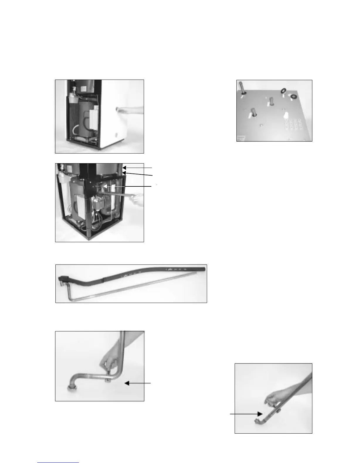
The right side plate has two
connection points. Swap right
and left side plates if you want
to connect on the left side.
Remove the plastic plugs from
the sideplate (1) and put them
in the holes on the roof cover
panel (2).
Remove both the heat transfer fluid pipes that go to the top of
the top plate. Heat transfer fluid in is equipped with a connector
on top of the heat transfer fluid pump. Heat transfer fluid out is
connected to the bottom of the heatexchanger. Note that the
sensor on heat transfer fluid out must first be removed.
The armaflex insulation is removed
from both pipes when removing the
heat transfer fluid pipe from the heat
pump.
Both heat transfer fluid pipes are cut to suit left or right mount-
ing. The following series of pictures provide the exact measure-
ments. The pipes are cut the same whether they are left or right
mounting.
Heat transfer fluid in
Heat transfer fluid out
Heat transfer fluid out
Sensor removed
Heat transfer fluid in
(1)
(2)
 Loading...


