50
Disconnection switch
• The heat pump must always have a main switch connected.
Earth leakage circuit breaker
• If the heat pump is connected over a leakage circuit breaker then a separate leakage circuit breaker is
recommended for the heat pump.
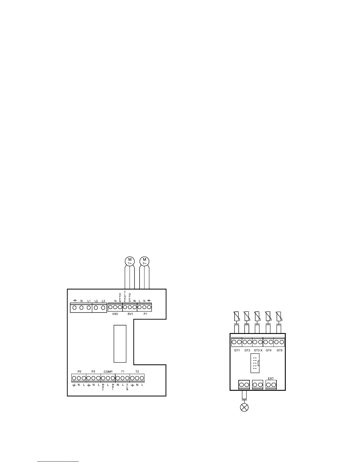
External connections in the C and E series.
• Power supply: Connect to terminals L1, L2, L3, N and PE. Alarm triggers if phases connected
wrongly.
• Heating cicuit with mixing valve: If a second heat curve with mixing valve is to be used, the mixing
valve is connected to terminals SV1.
• P1, external main pump in the heating system: Must always be connected. Connected to terminals
P1.
• Return sensor radiator GT1: Must always be connected. Connected to terminals GT1.
• Outdoor sensor GT2: Must always be connected. Connected to terminals GT2.
• Hot water sensor GT3: GT3 is connected if the heat pump is to produce hot water. Connected to
terminals GT3 X. (the C series is connected at factory).
• Mixing valve sensor GT4: Connected if the mixing valve for the second heat curve is used. Con-
nected to terminals GT4.
• Room sensor GT5: Connected if room sensor influence is required. Connected to terminals GT5. If
room sensor alarm is required it is connected to terminals ALARM LED.
Terminal
card
internal
couplings
Terminal
card internal
couplings
Return radiator
Out
Hot water
Mixing valve
Room
Mixing valve
P1
Alarm lamp, room sensors
ALARM
LED
GENERAL
ALARM
 Loading...


