Commissioning
Vent 402 – 6721815546 (2021/03)
16
6.2.2 Commissioning the control unit
The control unit automatically identifies which accessory modules are
installed in the system and adjusts the menu and default settings.
Select the Service menu. Enter the password that is the current date
+ 1 for each position. Example: June 29th = 0629 + 1 for each
position = 1730.
Open the Service > Commissioning menu.
Confirm each changed setting with d or with Confirm if it appears.
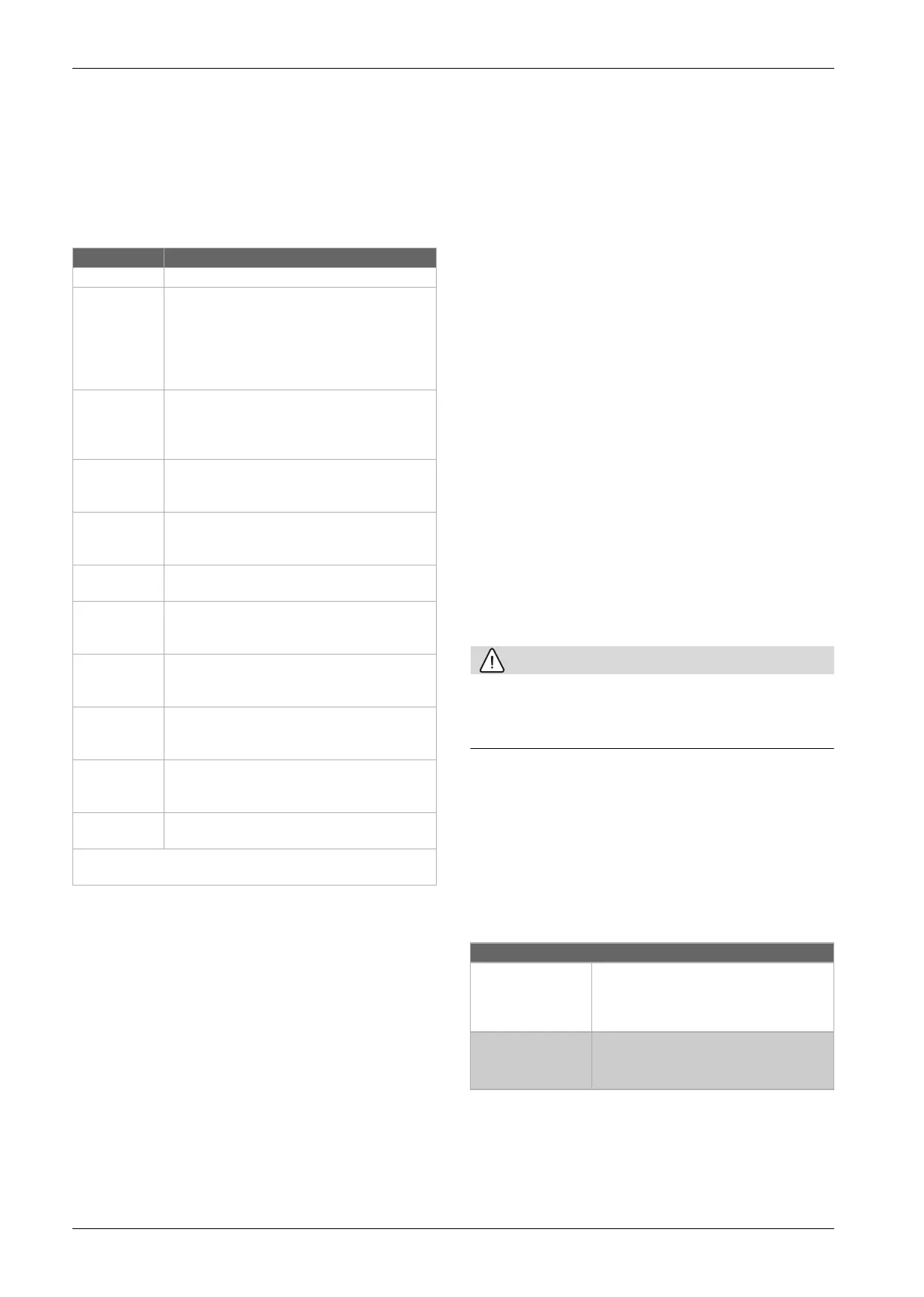
Table 8 Commissioning
6.2.3 Additional settings at commissioning
If corresponding functions are deactivated and modules, assemblies or
components are not installed, menu items that are not required are
disabled when continuing with additional settings.
Always remember to save all settings when the commissioning is done by
confirming Store installer settings in the service menu.
Important heating settings
Normally the relevant settings are done after system commissioning, but
if necessary further settings in the heating menu may be checked and
adjusted during commissioning.
Check settings in the menu for heating circuit 1 ... 2
( Chapter 7.8.1).
– Set Heating curve HC1 and Heating curve HC2 according to the
requirements of the system.
Important settings for the DHW system
The settings in the DHW menu must be checked and, if necessary,
adjusted during commissioning. This is important to make sure the DHW
heating is working properly.
Check the settings in the DHW system menu ( Chapter 7.8.2).
Important setting for additional systems or devices
If other specific systems or devices are installed in the system, additional
menu items will be available. This means that systems and devices are
available, for example a room controller.
Observe the relevant technical documentation of the system or device to
ensure proper function.
6.3 Venting
Check the pressure on the pressure gauge continuously during
ventilation. If the pressure drops below the desired value, the pressure
must be raised again via the filling valve. Do not let the pressure drop
below 0.5 bar. The pressure relief valve opens at 3 bar.
Make sure that all air vent valves are fully open. Note that the heat
pump has three air vent valves.
If the shut-off valves for the heating circuit are closed, open them.
Switch on the heat pump.
Start the venting function ( Chapter 8.4).
The venting function activates pumps, 3-way valve and electric
heater for about 20 minutes and then turns them off.
The venting function can be interrupted by turning it off, or by exiting
the Function tests menu.
CAUTION
Damage to the heating circuit due to overheating!
If the heat pump is installed in a heating system with a low heat output
(small heating circuit), the heat pump can superheat. This may lead to
damage in the heating circuit.
Go to the Service > Maintenance > Input signals info menu
Monitor the temperature in the heat pump's primary circuit and make
sure that the value TC1 primary supply temp at the radiator 65 °C
and the underfloor heating system 38 °C is not exceeded. If the
temperature increases, the venting function should be turned off
directly.
Leave the service menu and return to the customer main screen.
Check for alarms to ensure the heat pump is in standby mode.
6.4 Setting operating pressure for heating system
Table 9 Operating pressure
Fill to 2 bar unless otherwise indicated.
If the pressure is not maintained, check to ensure that the heating
system and expansion vessel are tight.
Menu item Description
Country Set the country.
Min. outdoor
temperature
Set the design temperature for the system, DUT
(Dimensioning outdoor temperature). This is the
lowest average outdoor air temperature for the
region. The setting affects the slope of the heat
curve, as it is the point where the heat source
reaches the highest flow temperature.
Only DHW
Production
This setting is used when replacing an older extract
air-to-water heat pump with a smaller electric heater.
Select [Yes] for DHW mode only.
Select Noif there is also a heating system installed.
Exhaust air heat
recovery
installed
Select [Yes] whether a supply air heater has been
installed. Otherwise choose No.
Heating system
HC1
Radiators | Convectors | Radiant floor heating: For
setting the type of heat distribution in the selected
heating circuit.
Max. temp non
floor HC1
1)
1) Alarm limit, make sure that the heat curve end point is set at a lower temperature.
For [Radiators] or [Convectors]: Set the maximum
flow temperature for heating circuit 1 and confirm.
Max. temp floor
HC1
For [Radiant floor heating] heat distribution: Set the
maximum flow temperature for heating circuit 1 and
confirm.
Heating system
HC2
Radiators | Convectors | Radiant floor heating: For
setting the type of heat distribution in the selected
heating circuit.
Max. temp non
floor HC2
For [Radiators] or [Convectors] distribution: Set the
maximum flow temperature for heating circuit 2 and
confirm.
Max. temp floor
HC2
For [Radiant floor heating] distribution: Set the
maximum flow temperature for heating circuit 2 and
confirm.
Fuse
2)
2) This menu appears only if an output limiter is installed.
16 A | 20 A | 25 A | 32 A: Adjust the main fuse of the
house as is intended for the heat pump.
Store installer settings: End the commissioning by saving the settings.
Return from [Commissioning] with d.
Indication on pressure gauge
1.0-1.3 bar Minimum filling pressure. If the heating system
is cold, the system must be filled to a pressure
of 0.2-0.5 bar above the pressure in the
expansion vessel.
3 bar Maximum filling pressure. At this pressure
the safety valve opens.
 Loading...


