Technical information
Vent 402 – 6721815546 (2021/03)
38
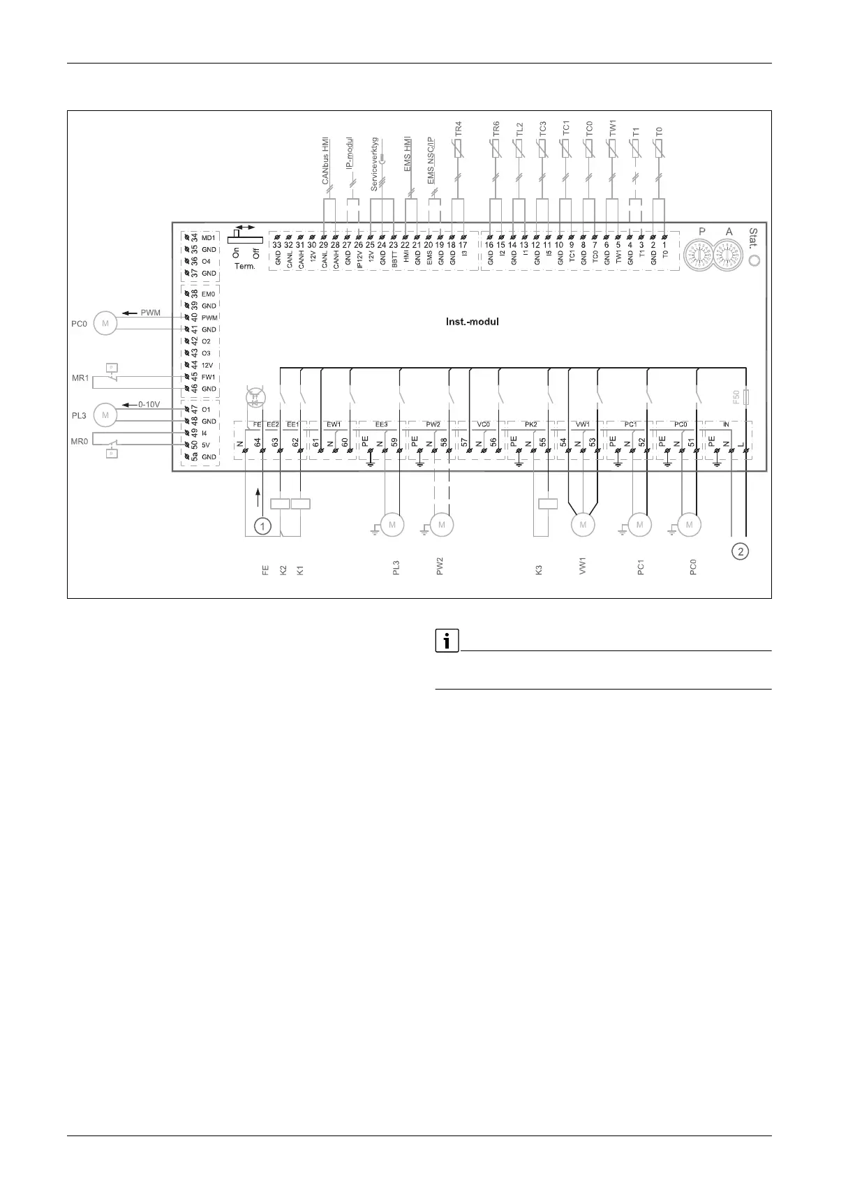
12.11.4 Installer module
Fig. 49 Installer module circuit diagram
Solid line = connected at factory
Dashed line = connected during installation
[1] Electric heater alarm
[2] ~ 230 V control voltage
[T0] Temperature sensor, flow
[T1] Outside temperature sensor
[TW1] Temperature sensor, DHW
[TC0] Temperature sensor returned
[TC1] Temperature sensor, flow
[TC3] Temperature sensor condenser out
[TL2] Air inlet temperature sensor
[TR6] Temperature sensor, hot gas
[TR4] Temperature sensor, evaporator
[PC0] Heat transfer medium primary circuit pump, 2 outputs:
power supply 230 V and activation pulse width modulation
[MR1] High pressure switch
[PL3] Fan, 2 outputs: power supply 230 V and activation 0–10 V
[MR0] Low pressure switch
[FE] Alarm overheating protection
[K2] Electric heater contactor EE2
[K1] Electric heater contactor EE1
[PW2] DHW circulation pump
[K3] Compressor relay ER1
[VW1] Diverter valve
[PC1] Circulation pump heating circuit
[F50] Fuse 6.3 A
Put CAN BUS termination switch in "ON" position.
P = A electric heater 13.5 kW 3 ~
P = 1 electric heater 9 kW 3 ~
P = 2 electric heater 1-2-3 kW 1 ~
A = 0 standard setting
Max. utilisation relay 2 A, cos >0.4. Max. circuit board total utilisation:
6.3 A.
0010020618-002
 Loading...


