Technical information
Vent 402 – 6721815546 (2021/03)
41
Fig. 52 Connection of network cable RJ45
[1] IP module
[2] Connection of network cable RJ45
Commissioning
Please refer to the router documentation during commissioning.
The router must be configured as follows:
• DHCP enabled.
• Ports 5222 and 5223 may not be blocked for communication.
• Free IP address available.
• The address filter (MAC filter) must not filter out the module.
At first startup:
• Connect the module to the Internet with an Internet router.
The module then connects automatically to the server. In the heat
pump display a symbol appears in the upper right. The module
receives the latest software.
• Establish a connection between the app and the heat pump.
• Enter the user name and password set by the factory (stated on the
module's nameplate).
• Enter the personal password. Note the password (optional with
data).
If you have forgotten your personal password:
• Reset the password on the control unit in the menu Settings >
Internet password
• Create a new personal password with the next app login.
Operation options:
• Internet
The module automatically requests an IP address from the router. The
name and address of the target server are stored in the standard settings
of the module. As soon as an Internet connection is established, the
module automatically logs on to the IVT server.
• Local network
The module must not be connected to the Internet. It can also be used in
a local network. In this case, however, the module cannot be reached via
the Internet, and the module software cannot automatically update.
• The app IVT Anywhere
When the App is started for the first time, the preset login name and
password must be entered. The login information can be found on the IP
module nameplate.
• SmartGrid
SmartGrid means that the unit can communicate with the electricity
market and adjust the operation so that the heat pump operates at its
maximum when the cost of electricity is lower. More information about
SmartGrid is available on the product home page.
12.13 Installation of accessories
12.13.1 CAN-BUS
NOTICE
The system will be damaged if the 12 V- and the CAN-BUS
connections are mixed!
The communication circuits are not designed for 12 V constant voltage.
Check to ensure that the cables are connected to the contacts with
the corresponding markings on the circuit board.
The various circuit boards in the heat pump are connected using a
communications line, CAN-BUS. CAN (Controller Area Network) is a two-
wire system for communications between microprocessor-based
modules.circuit boards.
• A suitable cable for external cable installation is wire LIYCY (TP)
2x2x0.75, or equivalent. An alternative cable should have a cross
section area of at least 0.75 mm
2
, and be a duplex cable, screened
and approved for outside use.
• Maximum cable length is 30 m.
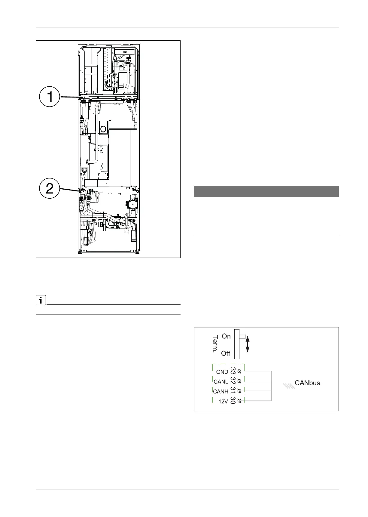
• Switches Term is used to mark the start and end of a CAN-BUS loop.
Ensure that the correct board is terminated and that all other
switches are in the opposite position.
Fig. 53 Termination CAN-BUS
On Terminated CAN-BUS
Off Not terminated CAN-BUS
• The connection is made with four wires, as the 12 V supply is also
connected. On the circuit board there is a marking 12 V and CAN-BUS
connections.
0010031334-001
10021436-001
 Loading...


