Technical information
Vent 402 – 6721815546 (2021/03)
39
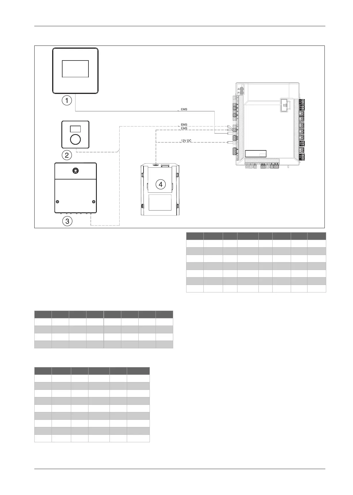
12.11.5 Circuit diagram EMS bus
Fig. 50 Circuit diagram EMS bus
Solid line= Connected at factory
Dashed line= Accessory
[1] HMC300 Control panel
[2] RC100H room controller
[3] MM 100 Mixing module
[4] IPI-100
12.11.6 Measurement values for temperature sensor
Temperature sensor in, or connected to, the heat pump (T0, T1, TR4,
TR6, TW1, TC0, TC1, TC3 and TL2) shall have the measurement values
shown in the table below.
Table 25 Water flows, DHW cylinder and inlet air temperature sensors
T0, TW1, TC0, TC1, TC3, TL2
Table 26 Outdoor and refrigerant evaporation temperature sensors T1,
TR4
Table 27 Refrigerant hot gas temperature sensor TR6
10021735-001
°C Ω °C Ω °C Ω °C Ω
20 12488 40 5331 60 2490 80 1256
25 10001 45 4372 65 2084 85 1070
30 8060 50 3605 70 1753 90 915
35 6536 55 2989 75 1480 - -
°C Ω.. °C Ω... °C Ω...
-40 154300 5 11900 50 1696
-35 111700 10 9330 55 1405
-30 81700 15 7370 60 1170
-25 60400 20 5870 65 980
-20 45100 25 4700 70 824
-15 33950 30 3790 75 696
-10 25800 35 3070 80 590
-5 19770 40 2510 85 503
0 15280 45 2055 90 430
°C Ω °C Ω °C Ω °C Ω
-20 198500 15 31540 50 6899 85 2123
-15 148600 20 25030 55 5937 90 1816
-10 112400 25 20000 60 4943 95 1559
-5 85790 30 16090 65 4137 100 1344
± 0 66050 35 13030 70 3478 105 1162
5 51220 40 10610 75 2938 110 1009
10 40040 45 8697 80 2492 115 879
 Loading...


