Technical information
Vent 402 – 6721815546 (2021/03)
29
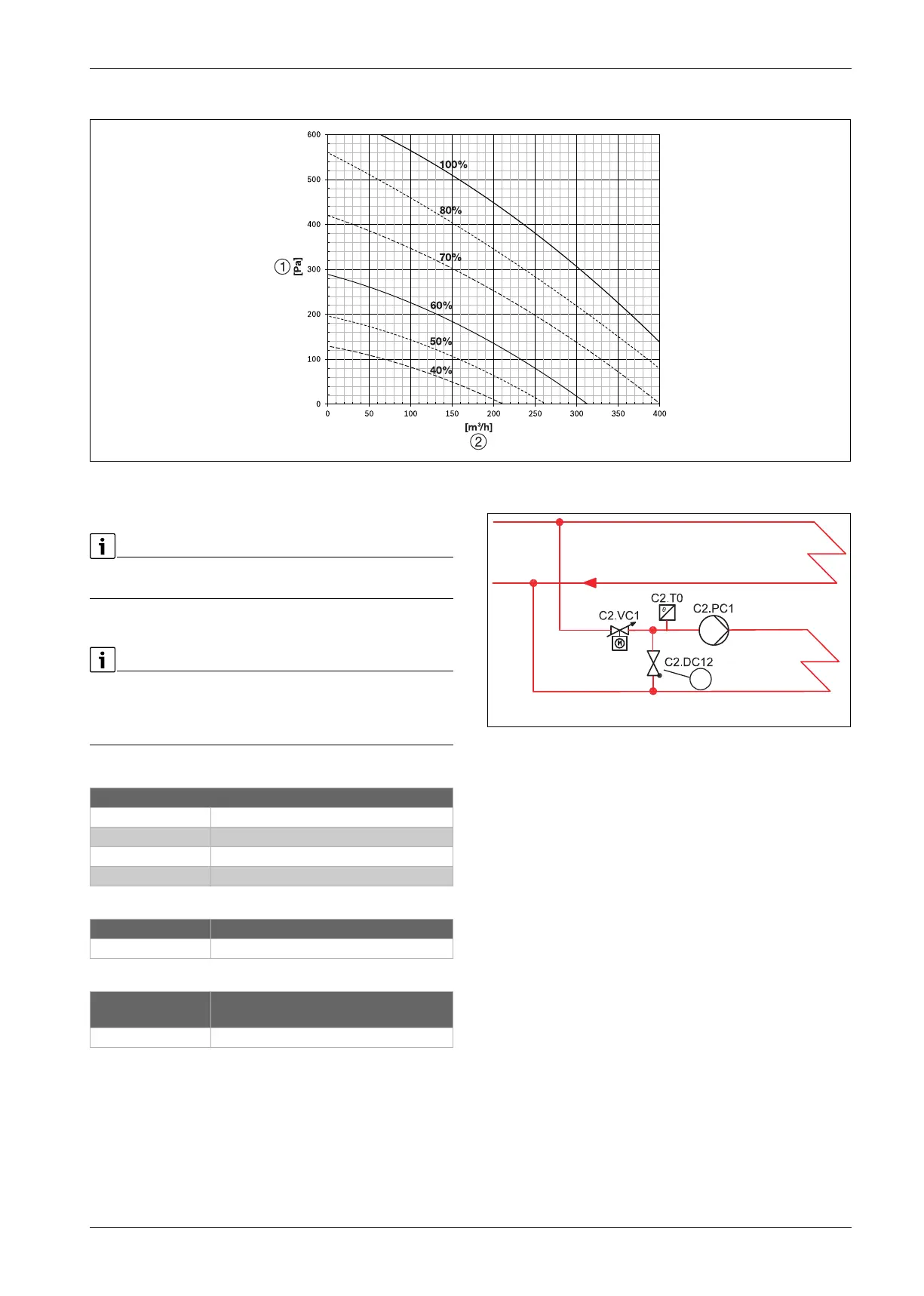
12.4 Ventilation curves
Fig. 40 Diagram pressure / airflow
[1] Pressure (Pa)
[2] Airflow (m
3
/h)
Pressure drop in the diagram refers to the external pressure drop caused
by the connected ventilation system.
12.5 System configurations
Heat pump may only be installed in accordance with the official system
configurations supplied by the manufacturer, other system
configurations are not permitted to be used. The manufacturer is not
liable for damages and problems caused by unauthorised installation.
System configuration explanations
Table 19 General
Table 20 Z1
Table 21 Z2/Z3
12.6 Non-return valve and bypass in heating circuit 2
Fig. 41 Heating circuit 2
[1] Non-return valve
A non-return valve is required to prevent self circulation in the heating
system.
The length of the bypass should be at least 10 times the inner diameter
of the pipe and have the same diameter as the heating circuit pipe.
General
Installer module Installer module integrated in the heat pump
Rego 3000 User interface
T1 Outside temperature sensor
T0 Flow temperature sensor
Z1 Heating circuit without mixing valve
T0 Flow temperature sensor
Z2/Z3 Heating circuit with mixing valve
(accessories)
MM100 Mixing valve module (controller for circuit)
10020831-004
1
 Loading...


