Function and operation
Vent 402 – 6721815546 (2021/03)
17
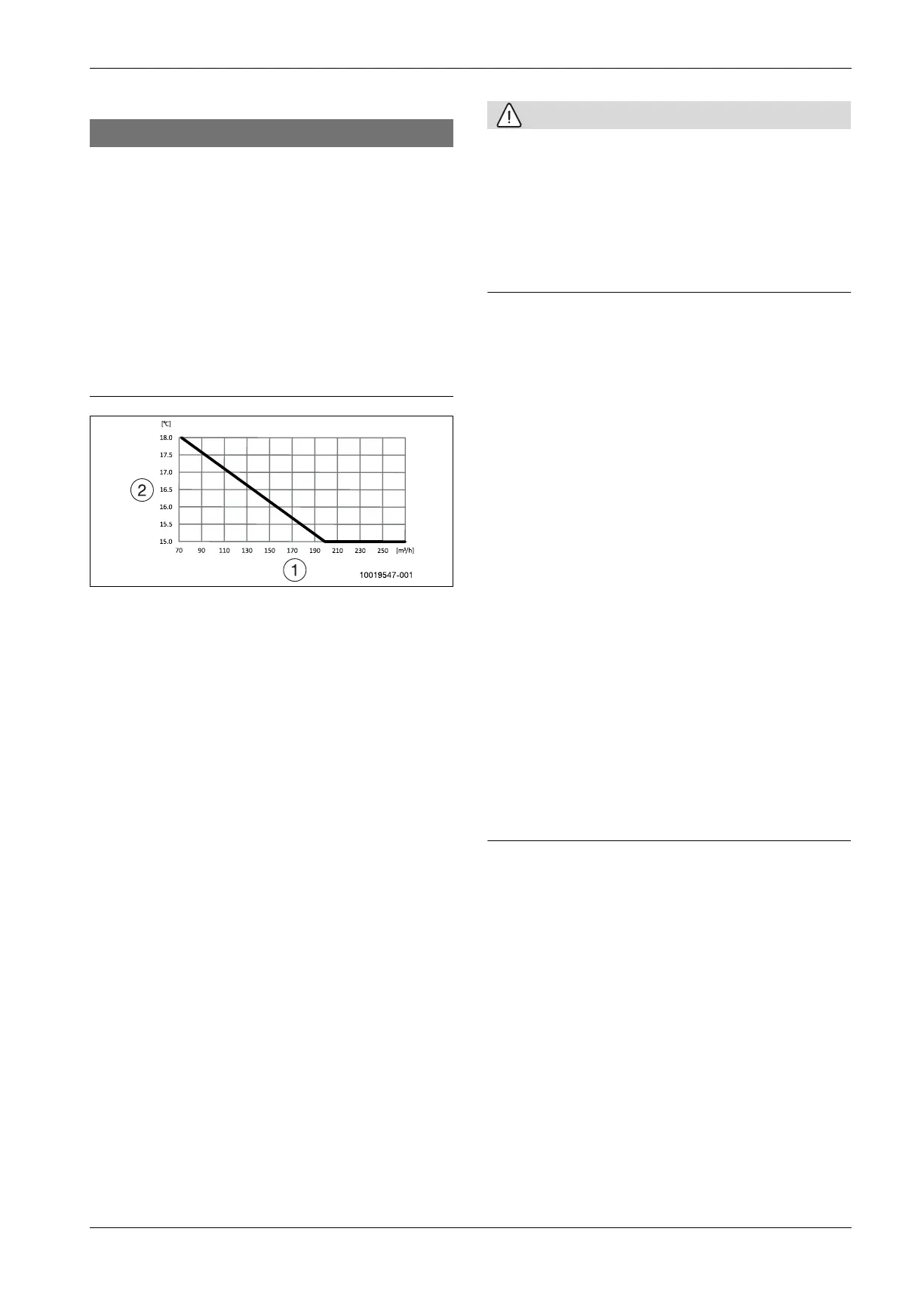
6.5 Minimum indoor temperature
NOTICE
Risk of defrosting problems or high energy consumption!
At low indoor temperatures in combination with low fan speeds,
defrosting problems or low pressure alarms can arise. To avoid this,
follow the recommendations below for minimum indoor air temperature
setting.
Do not set room temperature to lower than 18ºC if the airflow is set
at 70m
3
/h.
Do not set to a temperature decrease at night or holidays which will
cause the room temperature to drop below 18ºC if the airflow is set
at 70m
3
/h.
See the diagram for setting the lowest temperature in relation to
airflow.
Notify the user about the lowest indoor temperature for economic
operation.
Fig. 20 Lowest incoming air temperature for compressor operation
[1] Airflow
[2] Incoming air temperature (indoor temperature)
6.6 Adjustment of air flow / ventilation
This is performed by ventilation technicians for adjusting for correct air
flow, see ventilation drawing.
Adjust the ventilation as per the sizing information and settings in the
user interface (see table 7.7.1).
6.7 Function test
Vent the system (see Chapter 6.3).
Check the system's active components using the function check (
Chapter 8.4).
– Check that the primary pump PC0 works properly. To do this, set
PC0 prim heating pump to On.
– Change the primary pump speed with the variable PC0 speed and
check that the circulation pump reacts accordingly. At higher
speeds, the vibrations from the circulation pump become
stronger. To get a better feel for the pump operation, the speeds
70% and 100% can be compared to each other.
– Check that the heating circuit pump PC1 works properly. To do
this, set PC1 htg circ pump HC1 to On and check that the pump
LED lights green (and does not flash).
– Check that the 3-way valve works smoothly. Switch VW1 HW 3-
way valve between Off (heat) and On (DHW). The 3-way valve
should then change its position.
– Check that the compressor works without problems. To do this,
set Compressor to On. Check that the compressor is running. If
the compressor is switched off, it should not (be able to) turn it on
again immediately. If you turn the compressor OFF using Function
test, wait 10 min. to turn it back on again.
– Check that the electric heater works without problems.
CAUTION
Heat pump overheating!
Proceed carefully. The heating circuit valves must be open. To prevent
the heat pump from superheating, ensure that the temperature in the
primary circuit is below 40 °C.
Make sure that the value for TC3 current cond. temp, TC1 primary
supply temp and TC0 return temperature is below 40 °C. Input
signals infoTo check these temperatures, select .
To cool down the primary circuit turn both circulation pumps ON at
maximum speed, as described in the list above.
Turn on the electric heater's first step; set Auxiliary heater step 1 to
On. Use a voltage meter to check whether there is voltage in the
contactor K1 (upper contactor) on sockets 2T1, 4T2 and 6T3.
Disconnect again immediately. To ensure that the contactor works
without problems, the sockets 2T1, 4T2 and 6T3 must be checked
after the shutdown. There must be no voltage.
Turn on the second stage of the electric heater; set Auxiliary heater
step 2 to On. Use a voltage meter to check whether there is voltage in
the contactor K2 (lower contactor) on sockets 2T1, 4T2 and 6T3.
Disconnect again immediately. To ensure that the contactor works
without problems, the sockets 2T1, 4T2 and 6T3 must be checked
after the shutdown. There must be no voltage.
Check that the fan works without problems. Change the fan speed in
the menu Service > Heat source settings > Heat pump > PL3 fan
speed and check that the fan reacts accordingly.
Check that there is a demand for heat or hot water.
To generate a heat energy demand, raise the set point for the room
temperature. Press the heating icon on the display to do this. Note
that the heat pump operation does not start immediately. Wait at
least 10 minutes, to make sure that the heat pump has started to heat
up the heating system.
-or-
In order to generate a demand, draw off enough hot water so that the
tank cools down.
Check that the heat pump starts and that no alarm is activated.
6.8 System handover
Explain to the customer how the user interface and the accessories
work and how to operate them.
Inform the customer about the selected settings.
7 Function and operation
7.1 Connection principle
This principle is based on floating condensation and an integrated boost
from the electric heater. Via the control panel, the heat pump is regulated
according to the set heating curve. If the heat pump's heat output is not
sufficient to heat the house, the auxiliary heater starts automatically and
produces the desired temperature in the house together with the heat
pump. While the hot water cylinder is heating up, the heat system's heat-
regulated operation is temporarily disconnected by a 3-way valve. When
the hot water tank is heated, the heating system's heat-regulated
operation continues.
7.2 Anti-seizing
In summer mode, the control device ensures that key components such
as the circulation pump, exchange valve and any mixing valves
incorporate anti-seizing.
7.3 Radiators combined with underfloor heating
Where there is a combination of, e.g. underfloor heating and a radiator
system in which two different supply temperatures are required, an
 Loading...


