Installation
Vent 402 – 6721815546 (2021/03)
8
2. Disconnect the electrical connections (2 connectors)
3. Disconnect the hydraulic connections
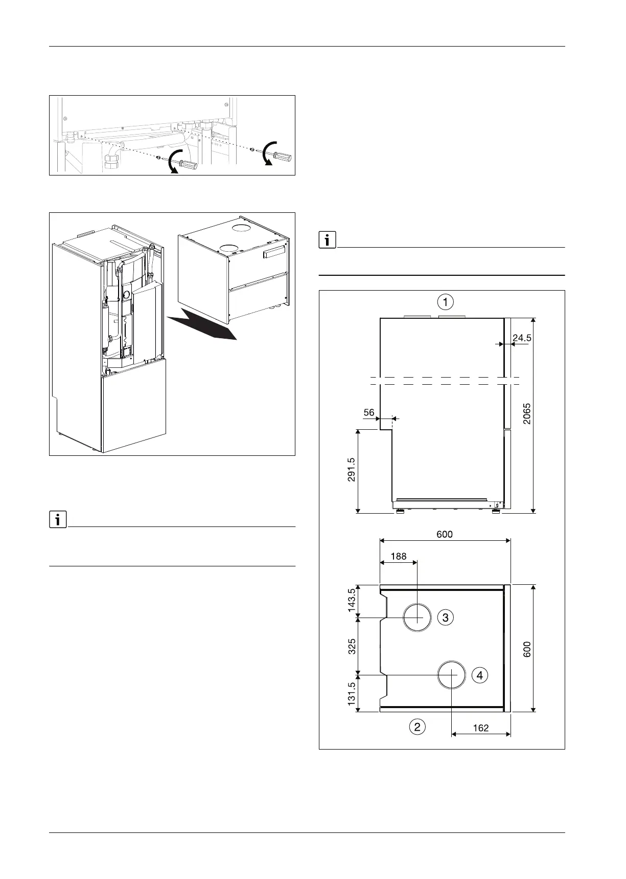
Fig. 9
Remove screws connecting the refrigerant box to the chassis
Fig. 10
Slide the refrigerant box out. The refrigerant box weighs 55.5 kgs.
5.2 Checklist
Each heat pump installation is unique. The heat pump installation
sequence is briefly summarized and described in more detail in each
following section.
1. Heat pump positioning - place the heat pump in an appropriate
location.
2. Hydraulic connections - connect the appliance to the heating
circuit, DHW circuit and the drain.
3. Air connections - connect the appliance to the house ventilation
system.
4. Electrical connections - connect all necessary sensors; connect any
necessary communication cable and connect the power supply to the
appliance.
5. Filling - fill the DHW tank, the appliance and heating circuit and turn
ON the appliance.
6. Commissioning - do the commissioning on the installer menu, adjust
the air flow according to protocol and inspect the water particulate
filters after start-up.
7. Purging - purge the system carefully.
5.3 Connections
5.3.1 Ventilation connections
Heat pump must be connected to a ducting system with a minimum
tightness class of B (as per current standards). May not be connected to
an air treatment system with heavy dust-laden or fat-saturated air or
from rooms containing combustible substances or gases which can enter
the heat pump.
Connection spigots
Dimension 125 mm diameter, fitted with rubber seal should be used.
Connection between heat pump and ducting system should incorporate
a short, flexible plastic hose in order to avoid vibration transfer.
Ducting insulation
Applicable regulations shall be observed. The output ducting from the
heat pump (exit air) must be insulated against condensation
continuously from the heat pump to the fitting to the top hood.
Otherwise, see ventilation drawing. The inlet duct should also be
insulated in order to damp sound.
With airflow in the lower end of the approved range, the lowest expected
exit air temperature is -6ºC.
[1] View from the side
[2] View from above
[3] Inlet airduct
[4] Outlet airduct
10021690-001
10021691-001
Front
10020637-004
 Loading...


