15 - 5
Descriptions (cont'd)
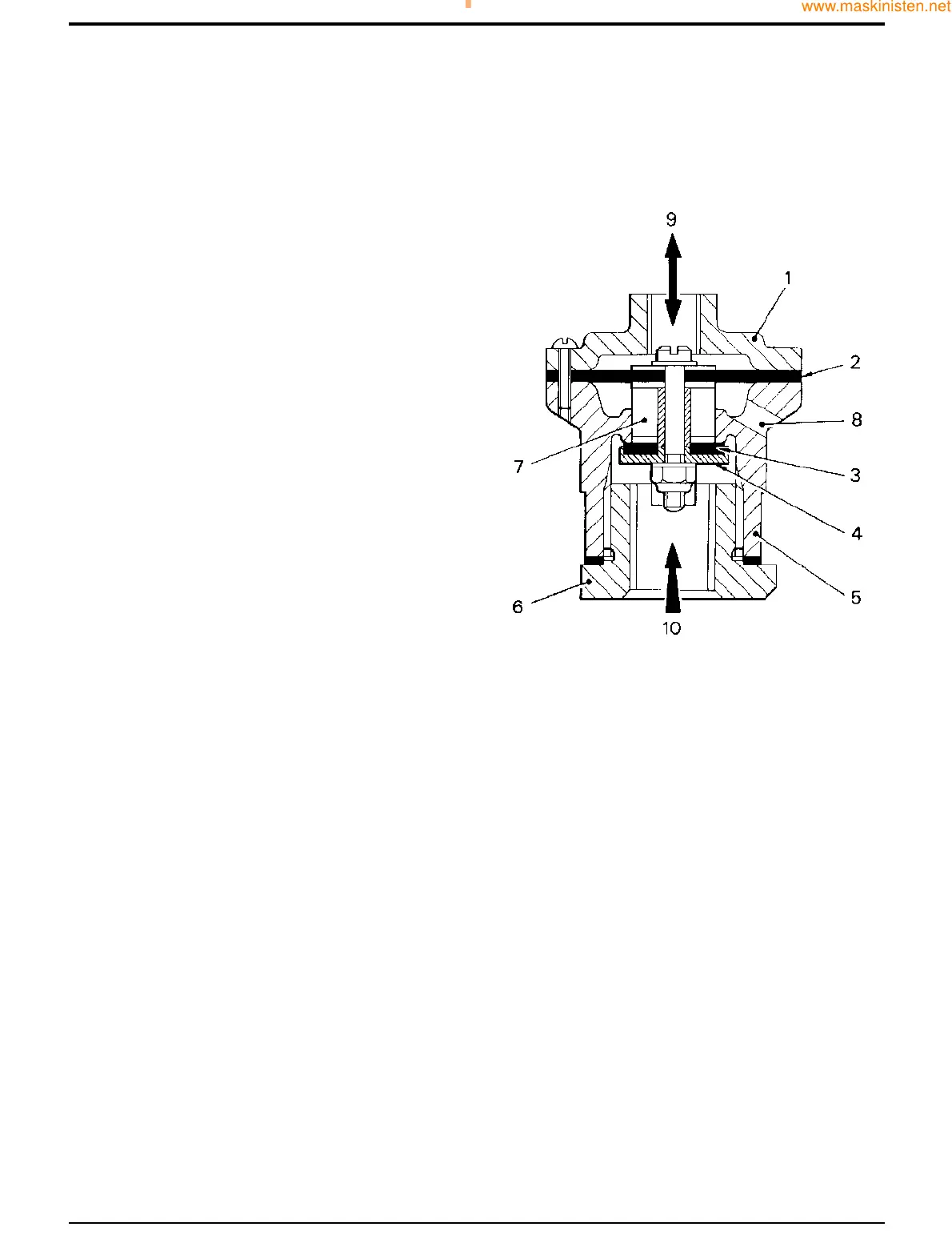
Blow Down Valve
The blow down valve is situated on top of the receiver. It
operates automatically to release all air pressure within the
system on shut-down, thus ensuring that the plant is not
started against delivery pressure.
The valve consists of a body 5 which contains a fluted valve
guide 7, valve 4 and valve seating washer 3. The valve
components are attached to a diaphragm, and the whole is
enclosed by a cap 1 at one end and a screwed cover 6 at
the other.
When the plant is running, a depression is created within the
unloader body which is applied to the top of the diaphragm
2 via inlet 9. Receiver air pressure 10 acts simultaneously
against the underside of the valve 4 and washer 3. The
washer is therefore retained firmly on its seat thus
preventing the escape of receiver pressure through ports 8
in the upper portion of the valve body.
On shut-down the delivery cocks are first closed, then the
engine is stopped. The residual pressure in the receiver
builds up within the unloader body (the unloader valve now
acting as a non-return valve as described on page A/15 - 4
and is applied to the top of diaphragm 2.
This pressure on the large area of diaphragm 2 is sufficient
to overcome the receiver pressure acting on the smaller area
of valve 4, therefore the washer 3 is lifted from its seat so
allowing the pressure still in the receiver to escape to
atmosphere through ports 8.
Section A Attachments
9803/7130
Section A
15 - 5
Issue 1
Airmaster Compressor
S211980
 Loading...