41 - 4
Drive Head Maxtrac - Assembly
The outline procedure below refers also to the following
aspects of the drivehead assembly, which are covered
separately in detail as sub topics later in this section:
Pinion Depth Setting
Collapsible Spacer Assembly
Crown Wheel and Pinion Meshing
Note: Both the crownwheel 15 and pinion 20 and the bevel
gears 9 and 10 are matched and should be renewed as sets
if any of their components are damaged or excessively
worn. The two differential housing halves 8A and 8B are also
matched. Do not use unmatched halves.
Make sure all bearings are lightly oiled before fitting and
setting. Make sure bearings are rotated whilst being set.
1 Determine the correct thickness required for the shims
23, refer to Pinion Depth Setting.
2 Fit shims 23 behind new bearing cup 22.
3 Fit new pinion head bearing cone 22 onto pinion 20.
4 Install pinion and bearings into the drive head casing.
Install largest available solid spacer 24 e.g (14.20 mm)
and fit pinion tail bearing 21 (lightly oiled). Do not fit the
oil seal 19 at this stage.
Note: In the absence of the special tools required or the
correct size solid spacer 24 it is acceptable to fit a
collapsible spacer, refer to Collapsible Spacer Assembly.
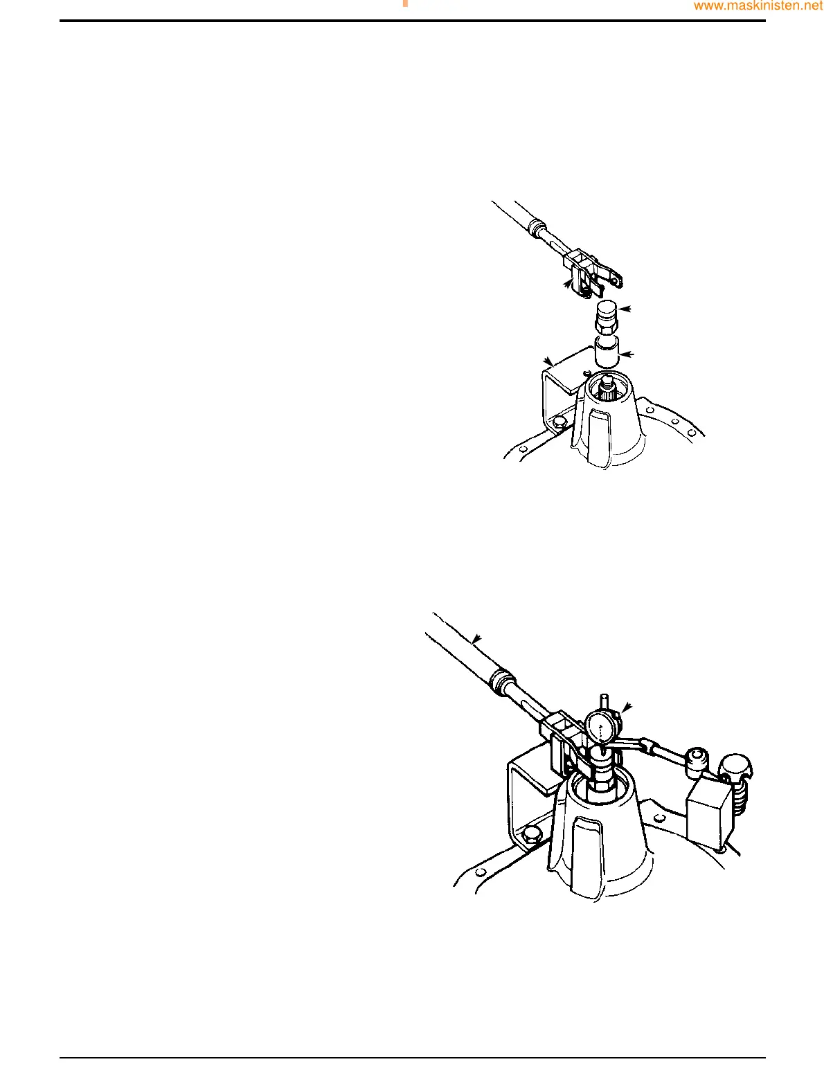
5 Fit special tool sleeve B and special pinion shaft
adapter C. Tighten adapter C to approximately 50 Nm,
making sure the pinion is free to rotate and there is end
float, this will prevent any damage to the bearing. If the
pinion is not free to rotate or there is no end float at this
stage check the bearing is fitted correctly. Also check
the correct size spacer has been fitted.
6 Fit special bracket D to the drive-head housing using
two M10 x 30 nuts and bolts. Fit special tool support
pillar E to bracket D so that the fork end engages in
adapter C. Ensure that fork E is centrally located on
adapter C. If necessary, re-align bracket D to suit.
7 Fit dial test indicator (DTI) F. Ensure that the DTI is
mounted on the drive head and not on bracket D.
8 Set torque wrench G to 35 Nm (25.8 lbf ft) and measure
the end float while rotating the shaft.
Section F Transmission
9803/7130
Section F
41 - 4
Issue 1
Front Axle
CC
BB
DD
348030
EE
FF
GG
348040
 Loading...