6
English
Milling cutter
2-sided clamp
Clamp handle
Slide
Slide handle
Fold-away stop
Tracer point
Start switch
Tracer point adjustment control
1
2
3
4
5
6
7
8
9
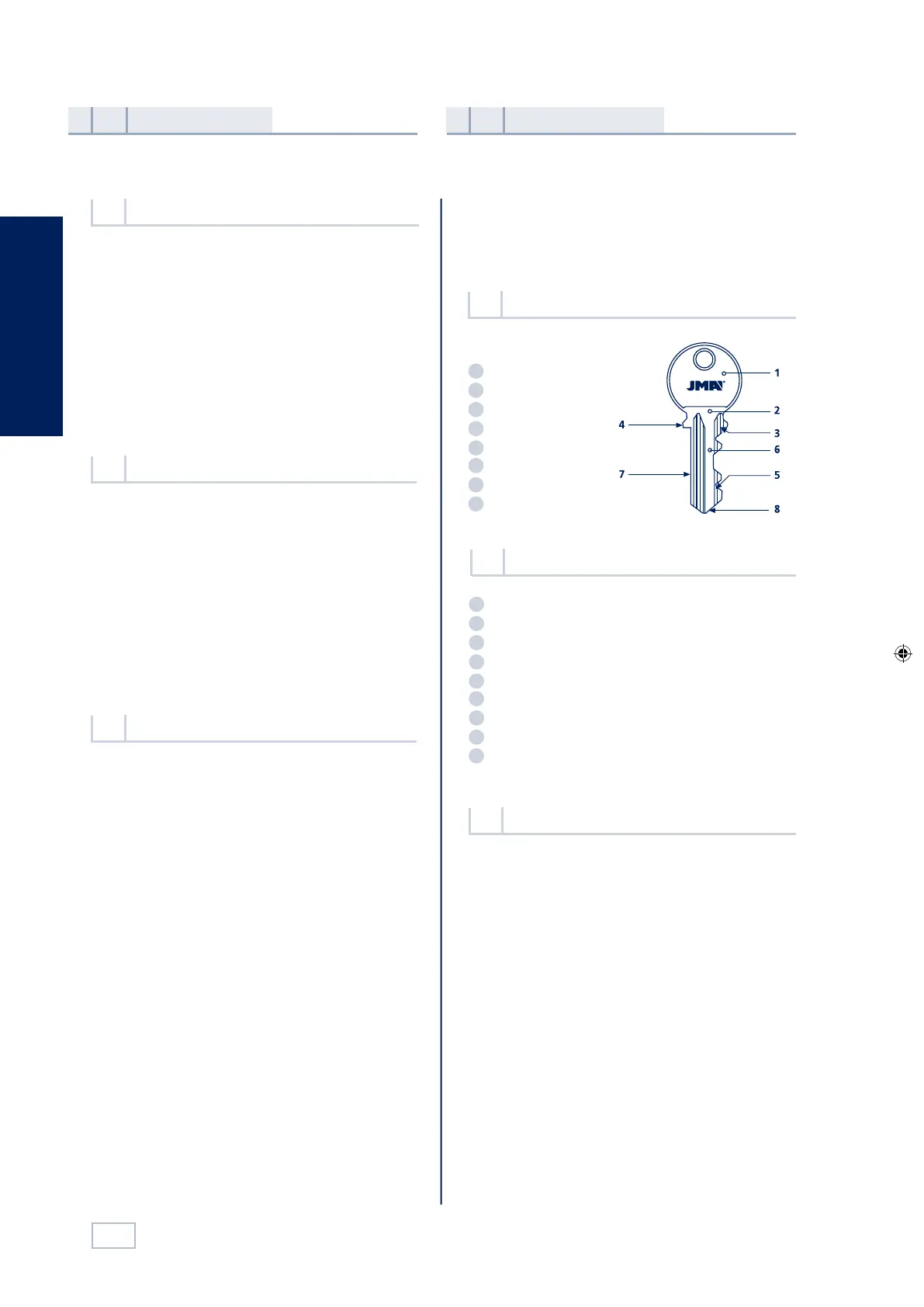
Head
Neck
Top shoulder
Bottom shoulder
Teeth
Blade
Back
Tip
1
2
3
4
5
6
7
8
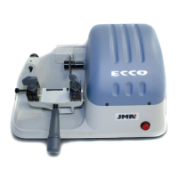
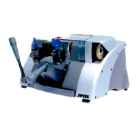
The ECCO machine is a robust and precise manual
machine for cutting flat cylinder lock keys, vehicle keys,
cross-shaped keys and special keys.
See Figure 2
Presentation
and general aspects
1
Characteristics
of the machine
2
The main technical information is as follows:
Motor: Single phase 220V, 50Hz, 0.18Kw,1500 rpm, 1.7 Amp.
or Single phase 110V, 60Hz,0.18Kw, 1800 rpm 3.14 Amp.
Milling cutter: Extra quick speed steel Ø63 x 16 x5 mm.
Speed: 1.500 rpm.
Clamps: 2 sided.
Displacement: On self-lubricated bearings.
Effective travel: X axis = 70 mm.
Dimensions:
Width = 470 mm, Depth = 245 mm,
Height = 280 mm.
Weight: 15 Kg.
Technical information
2.3
The ECCO key cutting machine has been designed
taking into account the safety standards currently in
force in the EU.
Although the machine is not difficult to install, it is best
not to try to install, adjust or use it without having first
read this manual.
The machine leaves our factory ready for use and only
requires the carrying out of calibration operations for
the tools that are going to be used.
The machine comes packed in packing of the following
size:
Width = 570 mm, length = 520 mm, height = 410mm
Machine weight plus packing = 18.5 Kg.
When the machine has been unpacked, check carefully
to see if it has suffered any damage during transporta-
tion. If you find any problems, please inform the carrier
immediately and do not do anything with the machine
until the carrier’s agent has carried out an inspection.
General points
1.1
The ECCO key cutting machine has an identification
label, giving the serial number, the name and address of
the manufacturer, the CE mark and the year of manu-
facture. See figure 1
Identification label
1.3
Transport and packing
1.2
Main elements of the machine
2.2
Parts of a key
2.1
6
English
Milling cutter
2-sided clamp
Clamp handle
Slide
Slide handle
Fold-away stop
Tracer point
Start switch
Tracer point adjustment control
1
2
3
4
5
6
7
8
9
Head
Neck
Top shoulder
Bottom shoulder
Teeth
Blade
Back
Tip
1
2
3
4
5
6
7
8
The ECCO machine is a robust and precise manual
machine for cutting flat cylinder lock keys, vehicle keys,
cross-shaped keys and special keys.
See Figure 2
Presentation
and general aspects
1
Characteristics
of the machine
2
The main technical information is as follows:
Motor: Single phase 220V, 50Hz, 0.18Kw,1500 rpm, 1.7 Amp.
or Single phase 110V, 60Hz,0.18Kw, 1800 rpm 3.14 Amp.
Milling cutter: Extra quick speed steel Ø63 x 16 x5 mm.
Speed: 1.500 rpm.
Clamps: 2 sided.
Displacement: On self-lubricated bearings.
Effective travel: X axis = 70 mm.
Dimensions:
Width = 470 mm, Depth = 245 mm,
Height = 280 mm.
Weight: 15 Kg.
Technical information
2.3
The ECCO key cutting machine has been designed
taking into account the safety standards currently in
force in the EU.
Although the machine is not difficult to install, it is best
not to try to install, adjust or use it without having first
read this manual.
The machine leaves our factory ready for use and only
requires the carrying out of calibration operations for
the tools that are going to be used.
The machine comes packed in packing of the following
size:
Width = 570 mm, length = 520 mm, height = 410mm
Machine weight plus packing = 18.5 Kg.
When the machine has been unpacked, check carefully
to see if it has suffered any damage during transporta-
tion. If you find any problems, please inform the carrier
immediately and do not do anything with the machine
until the carrier’s agent has carried out an inspection.
General points
1.1
The ECCO key cutting machine has an identification
label, giving the serial number, the name and address of
the manufacturer, the CE mark and the year of manu-
facture. See figure 1
Identification label
1.3
Transport and packing
1.2
Main elements of the machine
2.2
Parts of a key
2.1
7
English
2.4.2 Electric circuit See Figure 4
The main components of the electric circuit and
the electronic components are as follows:
1
2
3
Socket
Start switch
Motor
How the machine
works
3
Components and functional parts
2.4
Machine adjustement
3.1
4
5
1
2
3
Size 18 spanner.
Keys to adjust the height and depth of the
teeth.
Wedges to adjust the tip of the key.
Recessed wedges to cut cross-shaped keys.
Set of allen keys (2, 2.5, 3).
2.4.1 Accesories See Figure 3
2.4.3 2-sided clamp See Figure 5
The clamp is designed to secure a different family
of keys on each side. The figure shows the possibi-
lities for cutting on each side of the clamp.
1) Cutting the key with support on the back:
• Keys with normal blade
• Keys with narrow blade
2) Cutting by means of clamping the key by the
guide (profile).
3.1.1 Control and adjustment of the side distance
• Place the two adjustment keys (1) in the clamps, so
that the head of the adjustment key rests against
the inner stop of side 1 or 2 of the clamp.
• Then tighten the clamps.
• Move the clamps with the adjustment keys (1)
towards the tracer point (I) and the milling cut-
ter (F), so that the adjustment keys are in the
correct position in respect of the tracer point
and milling cutter. This is done by gently moving
the slide over the tracer point (I) and the milling
cutter (F).
See Figure 6.
• If the grooves of the adjustment key do not
coincide properly with the tracer point and the
milling cutter, proceed as follows:
• By gently loosening the shaft screws (T), you will
be able to move the milling cutter to the right
or left. You have to move the milling cutter to a
position in which it coincides with the groove of
the corresponding adjustment key. To carry out
this operation, you have to remove the motor
guard first.
• The distance is now perfectly adjusted, with the
tracer point and milling cutter coinciding with
the respective recesses of the adjustment keys.
Now tighten the shaft screws (T).
3.1.2 Control and adjustment of the cutting depth
• Place the two adjustment keys (1) in the clamps, so
that the head of the adjustment key rests against
the inner stop of side 1 or 2 of the clamp.
• Move the clamps with the adjustment keys (1)
towards the tracer point (I) and the milling cutter
(F), so that the adjustment keys rest on the tracer
point and the milling cutter.
• Turn the milling cutter by hand. If it gently rubs the
adjustment keys, the machine is properly adjusted.
• If the milling cutter turns freely, without rubbing,
this indicates that it is to far back in respect of the
tracer point and is not cutting deeply enough. On
the other hand, if the milling cutter becomes jam-
med up against the adjustment key, this indicates
that it is too far forward in respect of the tracer
point and is cutting too deeply.
• If either of these situations should occur, proceed as
follows:
- Undo the screw (L) securing the tracer point (I)
and turn the micrometric screw (H) See Figure 7.
- Move the tracer point forwards or backwards
until the milling cutter turns freely and rubs
gently against the adjustment key. Then tig-
hten the tracer point screw (L).The machine is
now in perfect working order.
man_ecco.indd 6 03/09/14 11:35
7
English
2.4.2 Electric circuit See Figure 4
The main components of the electric circuit and
the electronic components are as follows:
1
2
3
4
Socket
Start switch
Motor
Connection plate
How the machine
works
3
Components and functional parts
2.4
Machine adjustement
3.1
4
5
1
2
3
Size 18 spanner.
Keys to adjust the height and depth of the
teeth.
Wedges to adjust the tip of the key.
Recessed wedges to cut cross-shaped keys.
Set of allen keys (2, 2.5, 3).
2.4.1 Accesories See Figure 3
2.4.3 2-sided clamp See Figure 5
The clamp is designed to secure a dierent family
of keys on each side. The gure shows the possibi-
lities for cutting on each side of the clamp.
1) Cutting the key with support on the back:
• Keys with normal blade
• Keys with narrow blade
2) Cutting by means of clamping the key by the
guide (prole).
3.1.1 Control and adjustment of the side distance
• Place the two adjustment keys (1) in the clamps, so
that the head of the adjustment key rests against
the inner stop of side 1 or 2 of the clamp.
• Then tighten the clamps.
• Move the clamps with the adjustment keys (1)
towards the tracer point (I) and the milling cut-
ter (F), so that the adjustment keys are in the
correct position in
respect of the tracer point
and milling cutter. This is done by gently moving
the slide over the tracer point (I) and the milling
cutter (F).
See Figure 6.
• If the grooves of the adjustment key do not
coincide properly with the tracer point and the
milling cutter, proceed as follows:
• By gently loosening the shaft screws (T), you will
be able to move the milling cutter to the right
or left. You have to move the milling cutter to a
position in which it coincides with the groove of
the corresponding adjustment key. To carry out
this operation, you have to remove the motor
guard rst.
• The distance is now perfectly adjusted, with the
tracer point and milling cutter coinciding with
the respective recesses of the adjustment keys.
Now tighten the shaft screws (T).
3.1.2 Control and adjustment of the cutting depth
• Place the two adjustment keys (1) in the clamps, so
that the head of the adjustment key rests against
the inner stop of side 1 or 2 of the clamp.
• Move
the clamps with the adjustment keys (1)
towards the tracer point (I) and the milling cutter
(F), so that the adjustment keys rest on the tracer
point and the milling cutter.
• Turn the milling cutter by hand. If it gently rubs the
adjustment keys, the machine is properly adjusted.
• If the milling cutter turns freely, without rubbing,
this indicates that it is to far back in respect of the
tracer point and is not cutting deeply enough. On
the other hand, if the milling cutter becomes jam-
med up against the adjustment key, this indicates
that it is too far forwa
rd in respect of the tracer
point and is cutting too deeply.
• If either of these situations should occur, proceed as
follows:
- Undo the screw (L) securing the tracer point (I)
and turn the micrometric screw (H) See Figure 7.
- Move the tracer point forwards or backwards
until the milling cutter turns freely and rubs
gently against the adjustment key. Then tig-
hten the tracer point screw (L).The machine is
now in perfect working order.
6
1.20 mm rods
1.70 mm rods
7
man_ecco.indd 7 03/09/14 10:05
 Loading...