8
English
When carrying out maintenance operations, the follo-
wing requirements must be met:
Maintenance and
safety
4
• For segurity reasons, the manipulation of the keys and
machine have to be done with the motor turned off, the
red switch has to be at OFF position, the switch light is
off. The machine has to be start only when we are going
to cut the blank key.
• Insert the original key into the left-hand clamp, keeping
it a distance of 2 to 3 mm from the edge of the clamp.
See Figure 8.
• Tighten up the clamp, keeping the back of the key pro-
perly pressed against the base of the clamp.
• Insert the key blank to be cut into the right-hand clamp
and, before tightening up the clamp, raise the gauge (C)
and align the two keys. Ensure that the two pointers of
the gauge are resting firmly up against the top shoul-
ders of both keys. Finally, tighten up the clamps.
• Both the original key and the key blank to be cut should
be inserted in the left-hand side of the respective clamps.
• Withdraw the gauge (C). Start the machine and hold
the slide by means of the handle (M). Move the keys
towards the tracer point (I) and the milling cutter (F).
• Remember that you have to work from left to right.
Rest the original key against the tracer point and start
to work, moving the slide from right to left, using the
handle (M) and ensuring that the original key presses
gently against the tracer point.
• Once the key has been cut, return the slide to its initial
position, and don’t forget to turn OFF the machine to
stop the milling cutter. Then remove the keys by undo-
ing the clamps.
Key cutting operation
3.2
Do not try and start or handle the machine until all
safety matters, installation instructions, operator gui-
des and maintenance procedures have been fulfilled
and understood.
Always switch off the power supply before carrying
out any cleaning or maintenance operation.
Always keep the machine as well as its surroundings
clean.
Work with dry hands.
Use safety glasses, even if the machine is fitted with
guards.
Ensure that the machine is earthed.
Safety recommendations
4.2
Changing the milling cutter
4.1
3.2.1 Duplication of narrow bit key.
Use of rods 1.2 and 1.7
The rods are inserted between the bottom of the
clamp and the back of the key when the key to be
duplicated has a narrow bit. The rods prevent contact
with the clamp itself by making the key protrude
further. (See Figure 9).
3.2.2 Cutting keys without shoulders
Insert the two wedges (2) (see Figure.10) into the
vertical slots (R) of each clamp, depending on the
length of the key to be cut.
Rest the tips of the keys against the wedges (2).
The keys are now adjusted. Then tighten up the
clamps. Before starting to cut the key, it is advisa-
ble to remove the wedges.
3.2.3 Cutting cross-shaped keys.
Side 1 of the clamp
This type of key must be inserted into the clamps from
left to right. Place the wedges (5) (See Figure 11) with
the opening or recess facing upwards, in one slot or
the other (R), depending on the length of the key to
be cut.
The teeth of the key can be cut in three operations,
by turning and locking the shoulder of the key against
the wedge (5) each time.
Never carry out any maintenance operation with the
machine switched on.
Unplug the machine.
The indications in this manual must be strictly adhe-
red to.
Use original spare parts.
3
1
2
4
3
1
2
6
5
4
Undo the two milling cutter guard screws and remove
the guard.
To change the milling cutter: With the help of the two
size 18 spanners, lock the milling cutter shaft and undo
the nut (K) – left-hand thread – securing the milling cut-
ter (F). Then replace the milling cutter and finally put the
milling cutter guard back into place. See Figure.12
9
Deutsch
Fräser
2-seite Spannbacke
Handgriff der Spannbacke
Schlitten
Handgriff des Schlittens
Klappbarer Anschlag
Fühler
Schalter für Inbetriebnahme
Einstellvorrichtung für den Fühler
1
2
3
4
5
6
7
8
9
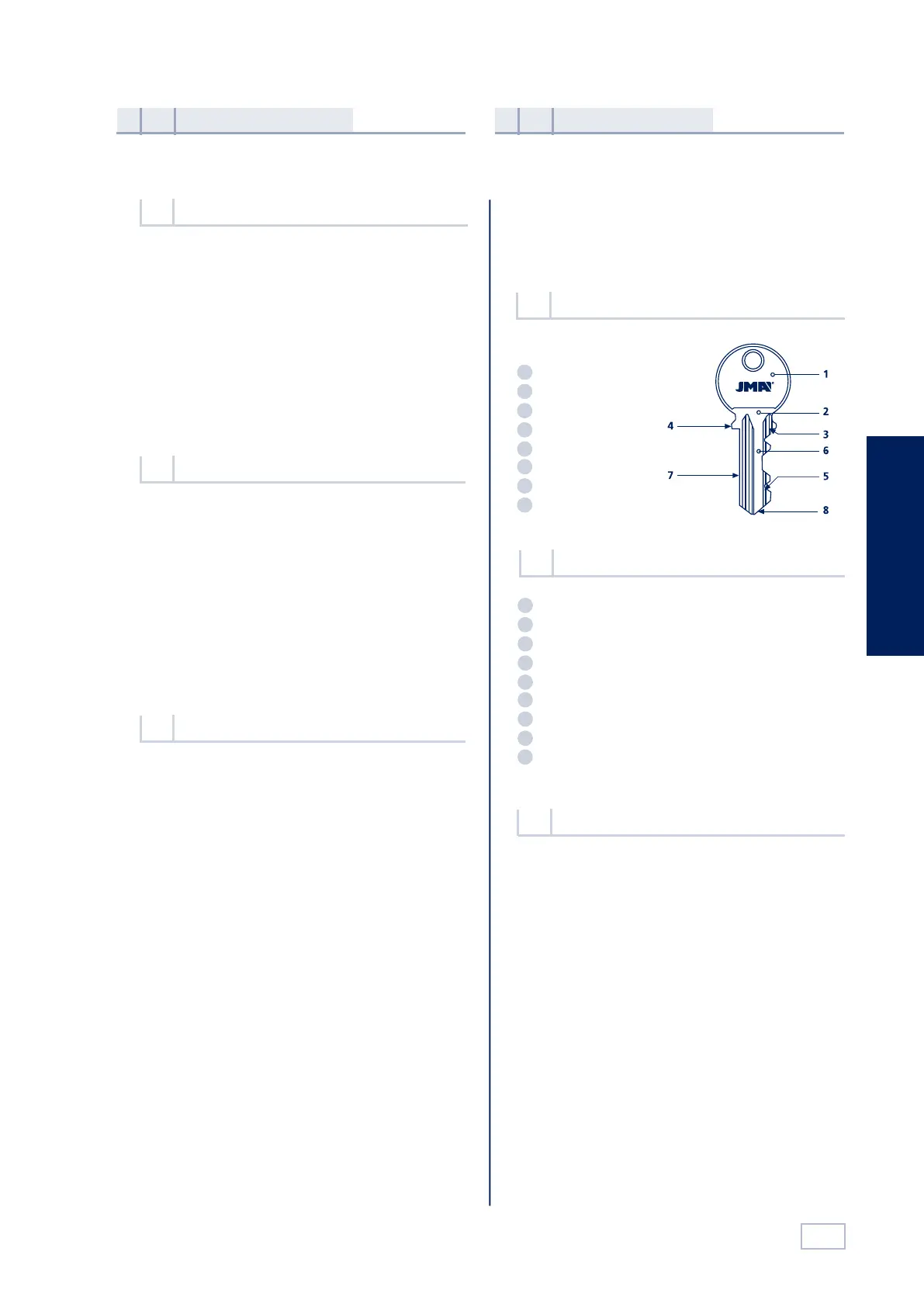
Schlüsselkopf
Schlüsselhals
Oberer Anschlag
Unterer Anschlag
Zahnung
Schlüsselbart
Schlüsselrücken
Schlüsselspitze
1
2
3
4
5
6
7
8
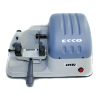
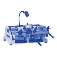
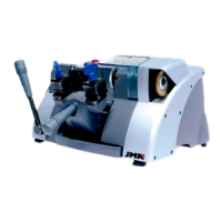
Bei der Maschine ECCO handelt es sich um eine äußerst
robust ausgeführte und präzise arbeitende manuelle
Kopiermaschine für Flachschlüssel für Zylinderschlösser,
Fahrzeugschlüssel, kreuzförmige Schlüssel und
Sonderschlüssel.
Siehe Abbildung 2
Vorstellung und
grundlegende begriffe
1
Eigenschaften
der maschine
2
Die Schlüsselkopiermaschine ECCO ist unter
Berücksichtigung der in der EU geltenden
Sicherheitsnormen entworfen worden.
Auch wenn die Installation der Maschine keinerlei
Schwierigkeiten bereitet, sollte sie nicht installiert,
eingestellt oder bedient werden, ohne zuvor das vorlie-
gende Handbuch gründlich gelesen zu haben.
Die Maschine ist werkseitig für den Gebrauch eingeste-
llt, so daß lediglich die Eichvorgänge für die zu verwen-
denden Werkzeuge vorzunehmen sind.
Die Maschine wird in einer Verpackung mit folgenden
Abmessungen ausgeliefert:
Breite = 570 mm, Länge = 520 mm, Höhe = 410mm
Maschinengewicht zusätzlich Verpackung = 18,5 kg.
Beim Auspacken der Maschine ist diese sorgfältig auf
eventuelle Transportschäden zu untersuchen. Sollten
Sie Beschädigungen feststellen, so wenden Sie sich bitte
umgehend an den Spediteur und belassen die Maschine
so wie sie ist, bis der zuständige Vertreter der Spedition
die entsprechende Überprüfung vorgenommen hat.
Allgemeines
1.1
An der Schlüsselkopiermaschine ECCO befindet sich
ein Typenschild, auf dem die Seriennummer, sowie
der Name und die Anschrift des Herstellers, die CE-
Kennzeichnung und das Baujahr angegeben werden.
Siehe Abbildung 1.
Typenschild
1.3
Die wichtigsten technischen Daten sind folgende:
Motor: Einphasig 220V, 50Hz, 0,18 kW, 1500 UpM, 1,7 Amp.
oder einphasig 110V, 60Hz, 0,18Kw, 1800 UpM, 3,14 Amp.
Fräser: Schnellarbeitsstahl Ø63 x 16 x5 mm.
Geschwindigkeit: 1.500 UpM.
Spannbacken: 2-seite.
Verfahrbewegung: Auf selbstschmierenden Lagern.
Verfahrweg: X-Achse = 70 mm.
Abmessungen: Breite = 470 mm, Tiefe = 245 mm,
Höhe = 280 mm.
Gewicht: 15 Kg.
Technische daten
2.3
Transport und verpackung
1.2
Hauptbestandteile der maschine
2.2
Nomenklatur des schlüssels
2.1
man_ecco.indd 8 03/09/14 11:35
8
English
When carrying out maintenance operations, the follo-
wing requirements must be met:
Maintenance and
safety
4
• For segurity reasons, the manipulation of the keys and
machine have to be done with the motor turned off, the
red switch has to be at OFF position, the switch light is
off. The machine has to be start only when we are going
to cut the blank key.
• Insert the original key into the left-hand clamp, keeping
it a distance of 2 to 3 mm from the edge of the clamp.
See Figure 8.
• Tighten up the clamp, keeping the back of the key pro-
perly pressed against the base of the clamp.
• Insert the key blank to be cut into the right-hand clamp
and, before tightening up the clamp, raise the gauge (C)
and align the two keys. Ensure that the two pointers of
the gauge are resting firmly up against the top shoul-
ders of both keys. Finally, tighten up the clamps.
• Both the original key and the key blank to be cut should
be inserted in the left-hand side of the respective clamps.
• Withdraw the gauge (C). Start the machine and hold
the slide by means of the handle (M). Move the keys
towards the tracer point (I) and the milling cutter (F).
• Remember that you have to work from left to right.
Rest the original key against the tracer point and start
to work, moving the slide from right to left, using the
handle (M) and ensuring that the original key presses
gently against the tracer point.
• Once the key has been cut, return the slide to its initial
position, and don’t forget to turn OFF the machine to
stop the milling cutter. Then remove the keys by undo-
ing the clamps.
Key cutting operation
3.2
Do not try and start or handle the machine until all
safety matters, installation instructions, operator gui-
des and maintenance procedures have been fulfilled
and understood.
Always switch off the power supply before carrying
out any cleaning or maintenance operation.
Always keep the machine as well as its surroundings
clean.
Work with dry hands.
Use safety glasses, even if the machine is fitted with
guards.
Ensure that the machine is earthed.
Safety recommendations
4.2
Changing the milling cutter
4.1
3.2.1 Duplication of narrow bit key.
Use of rods 1.2 and 1.7
The rods are inserted between the bottom of the
clamp and the back of the key when the key to be
duplicated has a narrow bit. The rods prevent contact
with the clamp itself by making the key protrude
further. (See Figure 9).
3.2.2 Cutting keys without shoulders
Insert the two wedges (2) (see Figure.10) into the
vertical slots (R) of each clamp, depending on the
length of the key to be cut.
Rest the tips of the keys against the wedges (2).
The keys are now adjusted. Then tighten up the
clamps. Before starting to cut the key, it is advisa-
ble to remove the wedges.
3.2.3 Cutting cross-shaped keys.
Side 1 of the clamp
This type of key must be inserted into the clamps from
left to right. Place the wedges (5) (See Figure 11) with
the opening or recess facing upwards, in one slot or
the other (R), depending on the length of the key to
be cut.
The teeth of the key can be cut in three operations,
by turning and locking the shoulder of the key against
the wedge (5) each time.
Never carry out any maintenance operation with the
machine switched on.
Unplug the machine.
The indications in this manual must be strictly adhe-
red to.
Use original spare parts.
3
1
2
4
3
1
2
6
5
4
Undo the two milling cutter guard screws and remove
the guard.
To change the milling cutter: With the help of the two
size 18 spanners, lock the milling cutter shaft and undo
the nut (K) – left-hand thread – securing the milling cut-
ter (F). Then replace the milling cutter and finally put the
milling cutter guard back into place. See Figure.12
9
Deutsch
Fräser
2-seite Spannbacke
Handgriff der Spannbacke
Schlitten
Handgriff des Schlittens
Klappbarer Anschlag
Fühler
Schalter für Inbetriebnahme
Einstellvorrichtung für den Fühler
1
2
3
4
5
6
7
8
9
Schlüsselkopf
Schlüsselhals
Oberer Anschlag
Unterer Anschlag
Zahnung
Schlüsselbart
Schlüsselrücken
Schlüsselspitze
1
2
3
4
5
6
7
8
Bei der Maschine ECCO handelt es sich um eine äußerst
robust ausgeführte und präzise arbeitende manuelle
Kopiermaschine für Flachschlüssel für Zylinderschlösser,
Fahrzeugschlüssel, kreuzförmige Schlüssel und
Sonderschlüssel.
Siehe Abbildung 2
Vorstellung und
grundlegende begriffe
1
Eigenschaften
der maschine
2
Die Schlüsselkopiermaschine ECCO ist unter
Berücksichtigung der in der EU geltenden
Sicherheitsnormen entworfen worden.
Auch wenn die Installation der Maschine keinerlei
Schwierigkeiten bereitet, sollte sie nicht installiert,
eingestellt oder bedient werden, ohne zuvor das vorlie-
gende Handbuch gründlich gelesen zu haben.
Die Maschine ist werkseitig für den Gebrauch eingeste-
llt, so daß lediglich die Eichvorgänge für die zu verwen-
denden Werkzeuge vorzunehmen sind.
Die Maschine wird in einer Verpackung mit folgenden
Abmessungen ausgeliefert:
Breite = 570 mm, Länge = 520 mm, Höhe = 410mm
Maschinengewicht zusätzlich Verpackung = 18,5 kg.
Beim Auspacken der Maschine ist diese sorgfältig auf
eventuelle Transportschäden zu untersuchen. Sollten
Sie Beschädigungen feststellen, so wenden Sie sich bitte
umgehend an den Spediteur und belassen die Maschine
so wie sie ist, bis der zuständige Vertreter der Spedition
die entsprechende Überprüfung vorgenommen hat.
Allgemeines
1.1
An der Schlüsselkopiermaschine ECCO befindet sich
ein Typenschild, auf dem die Seriennummer, sowie
der Name und die Anschrift des Herstellers, die CE-
Kennzeichnung und das Baujahr angegeben werden.
Siehe Abbildung 1.
Typenschild
1.3
Die wichtigsten technischen Daten sind folgende:
Motor: Einphasig 220V, 50Hz, 0,18 kW, 1500 UpM, 1,7 Amp.
oder einphasig 110V, 60Hz, 0,18Kw, 1800 UpM, 3,14 Amp.
Fräser: Schnellarbeitsstahl Ø63 x 16 x5 mm.
Geschwindigkeit: 1.500 UpM.
Spannbacken: 2-seite.
Verfahrbewegung: Auf selbstschmierenden Lagern.
Verfahrweg: X-Achse = 70 mm.
Abmessungen: Breite = 470 mm, Tiefe = 245 mm,
Höhe = 280 mm.
Gewicht: 15 Kg.
Technische daten
2.3
Transport und verpackung
1.2
Hauptbestandteile der maschine
2.2
Nomenklatur des schlüssels
2.1
man_ecco.indd 9 03/09/14 11:35
 Loading...