– 9 –
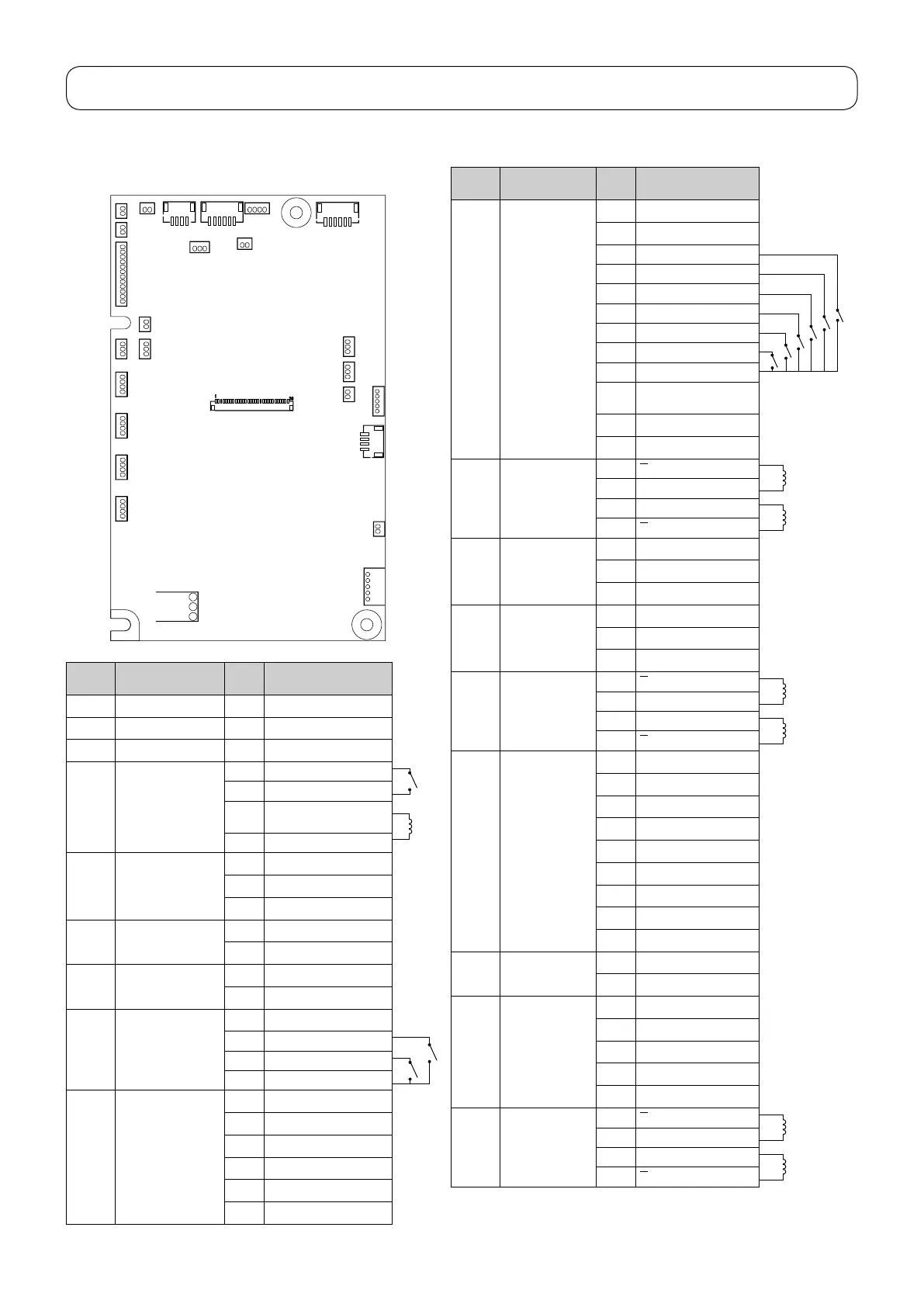
[5] PCB connection diagram
• Microcomputer PCB (Common to HZL-X Series)
Connec-
tor No.
Destination
Termi-
nal No.
CN1 On hand LED PCB 1 1 5V
CN2 Under arm LED PCB 1 5V
CN3 On hand LED PCB 2 1 5V
CN4 Bobbinwinding
motor
1 Bobbinwinderswitch
2 GND
3 Bobbinwindermotor(+)
(29V)
4 Bobbinwindermotor(-)
CN5 Presser-lifter STM
position detection
PCB
1 5V
2 Detection signal
3 GND
CN6 Flash memory inter-
face
1 5V
6 GND
CN7 OST SW (Not in-
stalled)
1 Presser foot lifting switch
2 GND
CN8 BH SW 1 GND
2 BHR SW
3 BHS SW
4 5V
CN9 Main shaft detection
PCB
1 5V
2 Motor pulse
3 S1
4 S2
5 S3
6 GND
Connec-
tor No.
Destination
Termi-
nal No.
CN10 SW/slide volume
PCB
1 LED G
2 LED R
3 Reverse stitch switch
4 S/S switch
5 Thread trimming switch
6 Needle up/down switch
7 Auto-lifter switch
8 Lock stitch switch
9 GND
10 Speedcontrolvariable
resistor
11 NC
12 5V
CN11 Presser-lifter STM 1
A
8.5Ω
2 A
3 B
8.5Ω
4
B
CN12 Thread trimming
STM original
point detection
PCB
1 Detection signal
2
3 GND
CN13 Presser-lifter STM
original point
detection PCB
1 Detection signal
2
3 GND
CN14 Needle throwing
STM
1
A
5.0Ω
2 A
3 B
5.0Ω
4
B
CN15 Panel PCB 1-3 LED
4-7
Switchstrobe
8-11
LCDbacklight
12-16
LCD signal
17 3.3V
18 GND
19-22
Rotary switch
23-29
Switch data
30 GND
CN16 For factory 2 GND
4 GND
CN17 Microcomputer
panelI/Fcable
(asm.)
1 5V
2 UART Tx
3 UART Rx
4 Clock signal
5 GND
CN18 Feed STM 1
A
4.0Ω
2 A
3 B
4.0Ω
4
B
CN22
CN20
CN16
CN17
CN24
CN25
CN26
CN15
CN9CN8CN6CN4CN3
CN5
CN7
CN1
CN2
CN10
CN23
CN13CN12
CN11
CN14
CN18
CN19
CN21
電源コントローラー製造用パネルI/F
主軸検知BH
フラッシュ書込み
下糸巻きLED2
LED1懐LED
スイッチスライドVR
糸切り原点押え針振り送り
糸切り
スライド針板
押え原点
押え高さ
押え上げ
(予備1)(予備2)(予備3)
模様選択
メインモーター
WHT BLU RED BLK WHT
GRN WHT
WHT
WHT GRN
RED
WHT WHT
WHT
BLU
BLK
WHT
WHT
WHT
WHT
WHT
 Loading...