– 31 –
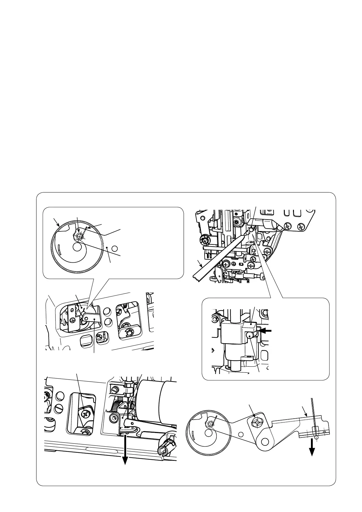
6-20 Automatic presser foot lifting
6-20-1 Auto-lifter cam lever
○
Remove the front panel and the microcomputer PCB.
Adjustmentprocedure
1.Checktobesurethatauto-liftercam
1
isatitsoriginposition(seethegurebelow).(TurnthepowerON
beforestartingtheadjustmenttobringauto-liftercam
1
to its origin position.)
2.Assemblethethroatplate.Assemblethestandardpresserfoot(presserfootA)inthepresserfootholder.
Lower the presser foot.
Atthistime,checktobesurethatthefeeddogdoesnotappearabovethetopsurfaceofthroatplate.
3. Loosen the setscrew
2
of the cam lever.
4. Place 0.3 mm thickness gauge
A
betweenpresserbarpositionbracket
3
and knee-lifter plate
4
. Press
cam lever arm
5
downward to remove the slack of wire. Then, tighten cam lever setscrew
2
.
1
6
B
C
6
1
Origin position:
Cam lever pin
B
must be positioned
on the left side of
cam mark
C
.
3
A
3
4
Place 0.3 mm
thickness gauge
A
in this section.
2
5
Press downward
2
5
Press downward
 Loading...