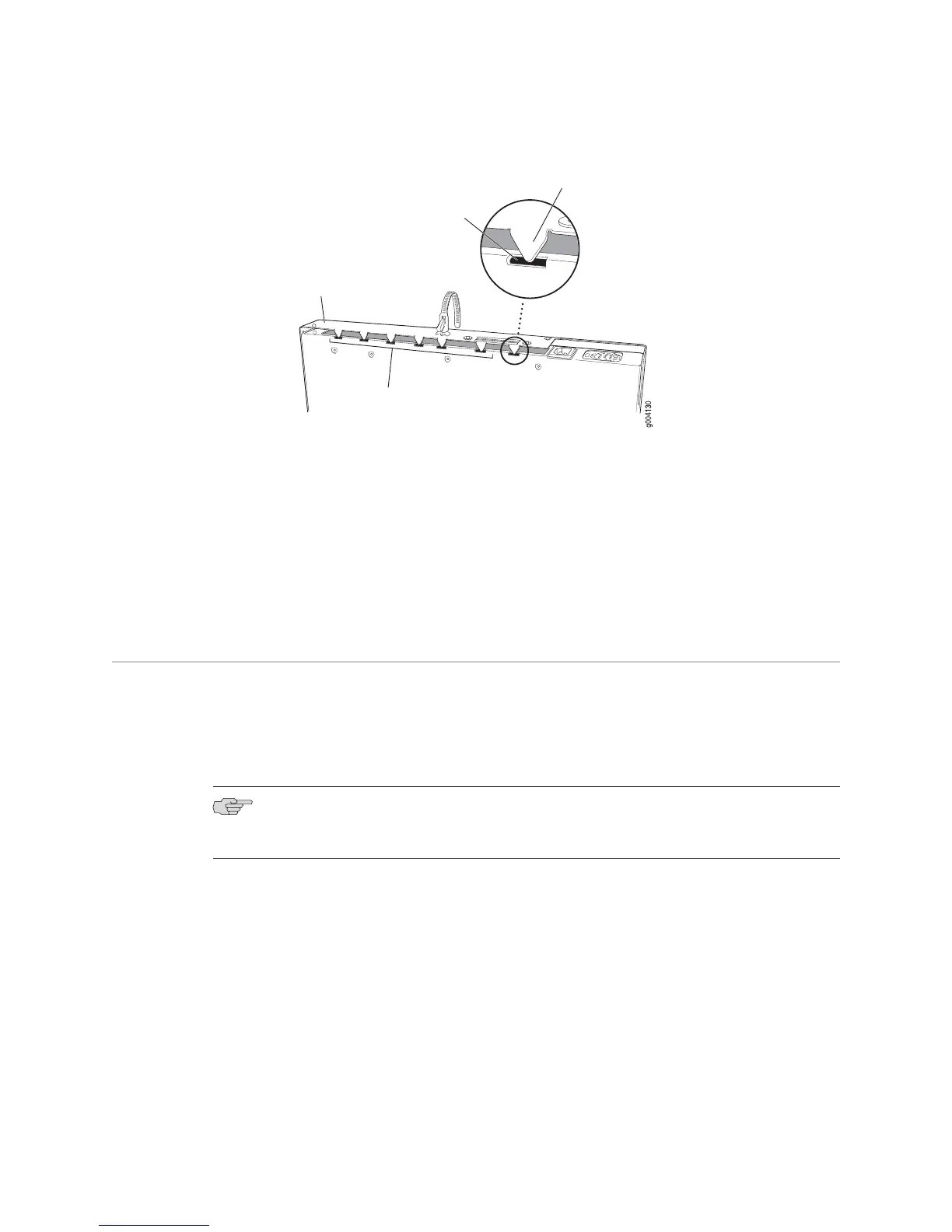
Figure 77: Matching the Chassis Slots and Tabs
3. Lower the cover fully onto the base, and slide it so that the front tabs match the
front slots and the chassis cover and base edges align completely.
4. Insert and tighten the flat head screws with a Phillips screwdriver.
5. Return the router to its installation site, and attach the grounding cable and the
power cables. (See “Connecting Power” on page 124.)
6.
Press and release the power button to power on the router. Verify that the POWER
LED lights steadily.
Replacing Internal Compact Flashes on J2320 and J2350 Routers
The internal compact flash provides primary storage for the router and is installed
in a slot on the bottom of the J2320 or J2350 chassis (see Figure 78 on page 179). It
can accommodate software images, configuration files, and microcode. For
information about configuring the internal compact flash, see the J-series Services
Router Administration Guide.
NOTE: Use only compact flash cards purchased from Juniper Networks for your
J-series platform and model.
178 ■ Replacing Internal Compact Flashes on J2320 and J2350 Routers
J2320, J2350, J4350, and J6350 Services Router Getting Started Guide
 Loading...