}
mep 700 {
interface ge-0/2/9.0;
direction down;
auto-discovery;
}
}
}
}
}
Related
Documentation
Ethernet OAM•
• Ethernet Operations, Administration, and Maintenance on page 103
• Ethernet OAM Connectivity Fault Management on page 104
• Example: Configuring Ethernet CFM on Bridge Connections on page 112
• Example: Configuring Ethernet CFM on Physical Interfaces on page 116
Example: Configuring Ethernet CFM on Bridge Connections
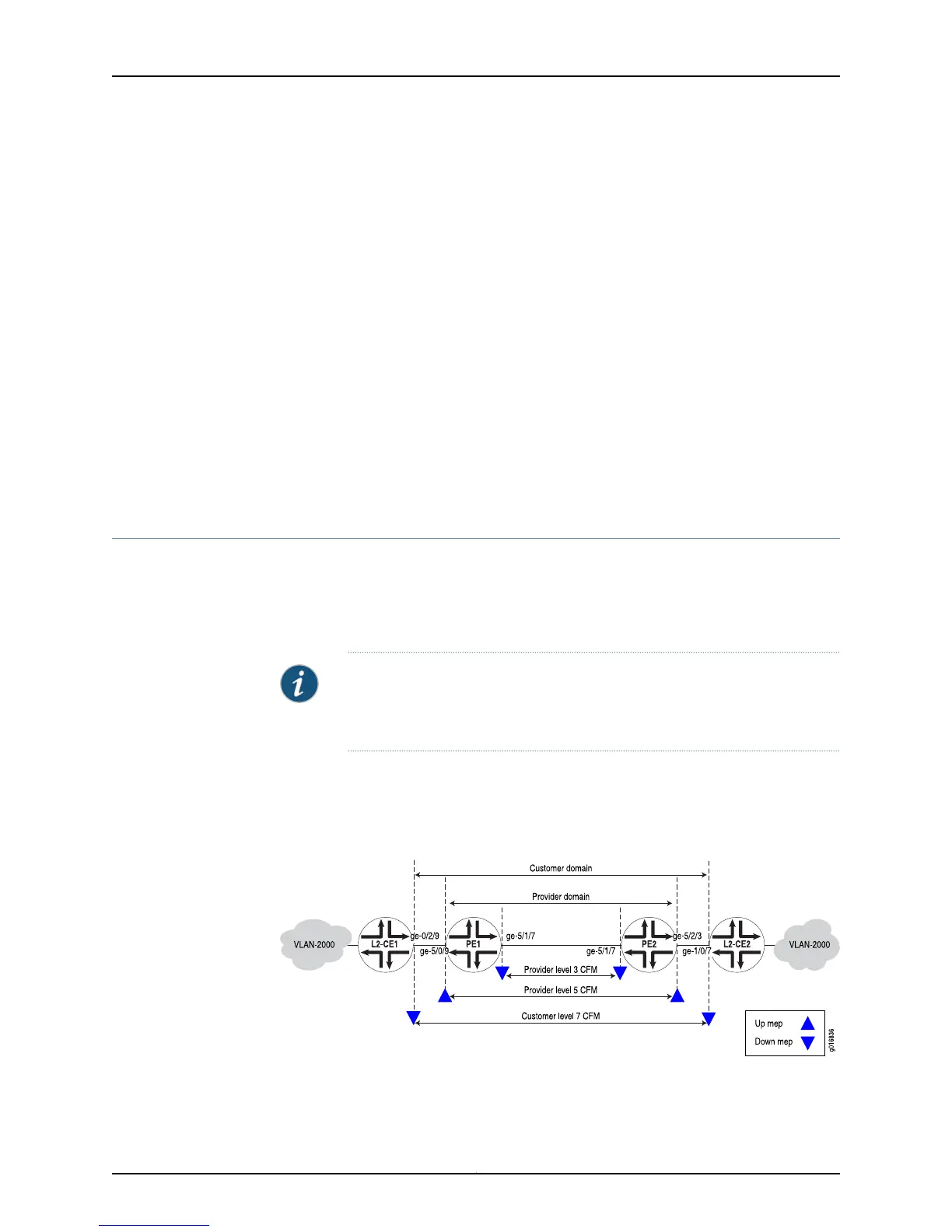
In this example, both the customer and service provider are running Ethernet CFM over
a simple bridge network. The network is shown in Figure 16 on page 112. The customer
has configured Ethernet CFM on MX Series routers L2-CE1 and L2-CE2. The service provider
has configured Ethernet CFM on MX Series routers PE1 and PE2.
NOTE: The configurations in this example are only partial examples of
complete and functional router configurations. Do not copy these
configurations and use them directly on an actual system.
The service provider is using CFM level 3 for the link between PE1 and PE2 and level 5
from one CE facing port to the other. The customer is using CFM level 7. The boundaries
are marked with “up mep” and “down mep” CFM terminology in the figure.
Figure 16: Ethernet CFM over a Bridge Network
Here are the configurations of CFM on the customer routers.
Copyright © 2012, Juniper Networks, Inc.112
Junos OS 12.1 MX Series 3D Universal Edge Routers Solutions Guide
 Loading...


