Filename [DR-MV1SE_04Name.fm]
Masterpage:Left0
16 EN
Page 16 March 11, 2004 7:27 pm
INSTALLING YOUR NEW UNIT
It’s essential that your unit be properly connected.
1 Make sure the package contains all of the accessories listed in
“SPECIFICATIONS” on page 95.
2 Place the unit on a stable, horizontal surface.
3 Connect the unit to a TV depending on the TV and cables you
use.
Basic Connection
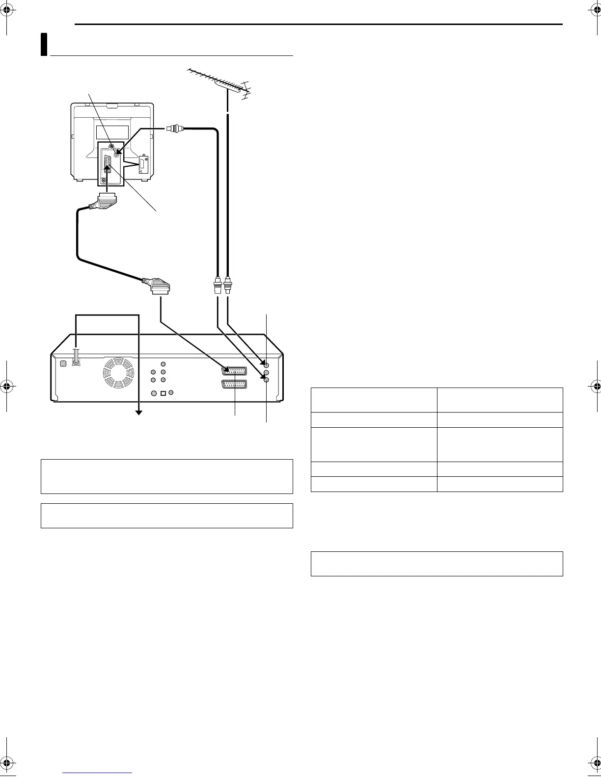
8 To connect to a TV with AV input connectors —
A Disconnect the TV aerial cable from the TV.
B Connect the TV aerial cable to the ANTENNA IN connector on
the rear panel of the unit.
C Connect the ANTENNA OUT connector on the rear panel of the
unit and the TV’s aerial connector with the provided RF cable.
D Connect the L-1 IN/OUT connector on the rear panel of the unit
and the TV’s 21-pin SCART connector with a provided 21-pin
SCART cable.
● The L-1 IN/OUT connector accepts and delivers either a composite
signal (regular video signal), Y/C signal or RGB signal.
● Set your TV to the VIDEO (or AV), Y/C, or RGB mode according to
the type of your TV’s SCART connector.
8 Component Video Connection (DVD deck only)
To connect to TV’s component video input connectors
A Perform A – C in “Basic Connection”.
B Connect the unit’s COMPONENT VIDEO OUT connectors to
the TV’s component video input connectors.
C Connect the unit’s AUDIO OUT connectors to the TV’s AUDIO
input connectors.
● You can obtain high-quality component video pictures.
● If your TV is not stereo-capable, use the unit’s AUDIO OUT
connectors to connect to an audio amplifier for Hi-Fi stereo sound
reproduction.
● By using the component video connection, you can view the images
in the progressive mode. For switching to the progressive mode, refer
to “Scan Mode Set” (
墌 pg. 88).
NOTE:
Select an appropriate option of “L-1 OUTPUT” as follows (墌 pg. 72):
4 Plug the end of the AC power cord into an AC outlet.
● “LOADING” blinks on the front display panel when the AC plug of the
power cord is connected into a mains outlet and it takes
approximately 50 seconds for the unit to be turned on. This is not a
malfunction.
Basic Connection
TTENTION:
Your TV must have a 21-pin AV input connector (SCART) for the
connection to the unit.
THESE STEPS MUST BE COMPLETED BEFORE ANY VIDEO
OPERATION CAN BE PERFORMED.
2
RF cable
(provided)
Back of unit
Back of TV
TV aerial cable
21-pin SCART connector
21-pin SCART cable
(provided)
Mains power cord
ANTENNA IN
L-1 IN/OUT
ANTENNA OUT
Mains outlet
Aerial connector
When your TV’s SCART
connector accepts:
Set “L-1 OUTPUT” to:
Composite signals “SCART VIDEO”
Y/C signal (separated
luminance (brightness) and
chrominance (colour) signals)
“SCART S-VIDEO”
RGB signal “SCART RGB”
Component video signal “COMPONENT”
After connection is completed, perform “Auto Set Up” on
page 17.
DR-MV1SE_00.book Page 16 Thursday, March 11, 2004 7:28 PM
 Loading...