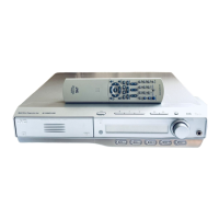
Connections Thispageisfor ITH-M303I[TN-N301]
Before connecting the
speaker cords;
Twist and pull the
insulation coat off and
rentove.
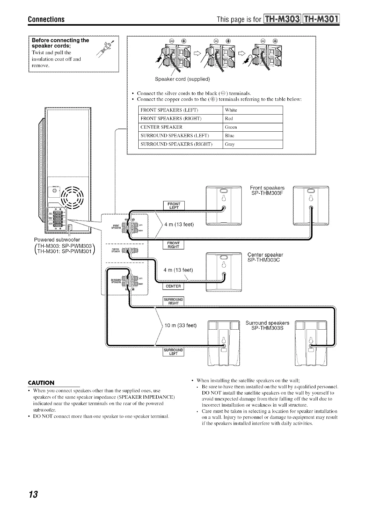
Speaker cord (supplied)
• Connect the silver cords to the black (@) terminals.
• Connect the copper cords to the (@) terminals referring to the table below:
FRONT SPEAKERS (LEFT) White
FRONT SPEAKERS (RIGHT) Red
CENTER SPEAKER Green
SURROUND SPEAKERS (LEFT) Blue
SURROUND SPEAKERS (RIGHT) Gray
Front speakers
SP-THM303F
Powered subwoofer
TH-M303: SP-PWM303_
TH-M301 : SP-PWM301 ]
4 m (13 feet)
4 m (13 feet)
Center speaker
SP-THM303C
10 m (33 feet)
Surround speakers
SP-THM303S
CAUTION
• When you connect speakers other than the supplied ones, use
speakers of the same speaker impedance (SPEAKER IMPEDANCE)
indicated near the speaker terminals on the rear of the powered
subwoofer.
• DO NOT connect more than one speaker to one speaker terminal.
• When installing the satellite speakers on the wall;
• Be sure to have them installed on the wall by a qualified personnel.
DO NOT install the satellite speakers on the wall by yourself to
avoid unexpected damage li'nm their falling off the wall due to
incorrect installation or weakness in wall structure.
• Care must be taken in selecting a location for speaker installation
on a wall. lnjury to personnel or damage to equipment may result
if tl_e speakers installed interfere with daily activities.
13
 Loading...