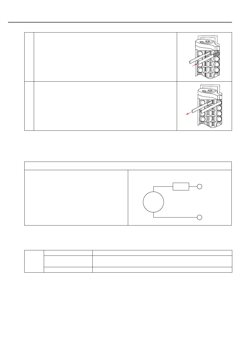
3. Plug cable into the round slot, that no wires can be seen
from the outside.
4. Remove screw driver and check if cables are xed.
2.3.2 Voltage supply of the control
The voltage for supply of the control (US) occurs via terminals X2.9 and X2.10 in accordance
with picture 2.3.2 and is electrically insulated from UM. If the control is supplied with voltage,
the VCC-LED ashes (green).
Picture 2.3.2 Voltage supply of the control
U = 18…30 V DC ±0 %
F1 = 2 A type gG
2.3.3 Voltage supply for the inputs and outputs
The voltage for supply of the digital inputs and outputs (UM) occurs via the terminals X2.1 to
X2.8 in accordance with picture 2.3.3 and is electrically insulated from US.
%IW1
%IX1.0 Condition of the supply voltage in/outputs (UM)
%IX1.1
Is set in case of overload at one or several outputs. Additio-
nally the OL-LED (red) is set.
%IX1.2…%IX1.15 not assigned

 Loading...

