Picture 2.3.3 Voltage supply for the inputs and outputs
U = 18…30 V DC ±0 %
F2 = 6,3 A type gG
2.3.4 Digital inputs (X2.11…14)
The digital inputs are potential-free to the control voltage US.
4 digital inputs 0...3
%IW0
%IX0.0…%IX0.3
Condition of the digital inputs 0…3 not assigned
%IX0.4…%IX0.15
Picture 2.3.4 Connection of the digital inputs
Potential-free connection Connection e.g. via PLC
+
-
X2.2 (+UM)
X2.5 (- UM)
X2.12 ( I1 )
П
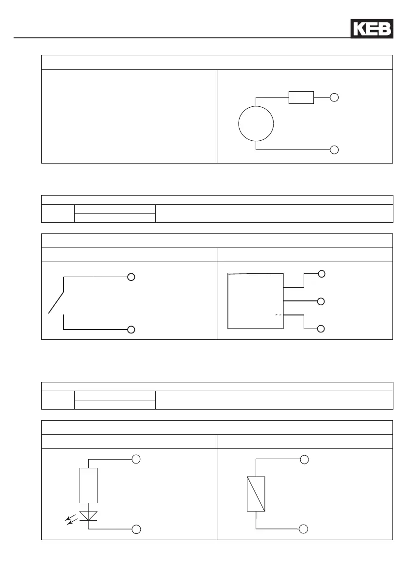
2.3.5 Digital outputs (X2.15…18)
The digital outputs are potential-free to the control voltage US. A free-wheeling diode is inte-
grated in the unit, so that no external wiring is necessary at inductive load.
4 digital outputs 0...3
%QW0
%QX0.0…%QX0.3
Condition of the digital outputs 0…3 not assigned
%QX0.4…%QX0.15
Picture 2.3.5 Connection of the digital outputs
Ohmic load Inductive load

 Loading...

