38
L3
++
--
PB
U
V
W
X1A
M
3~
L1
N/L2
T1
T2
PE
U
V
W
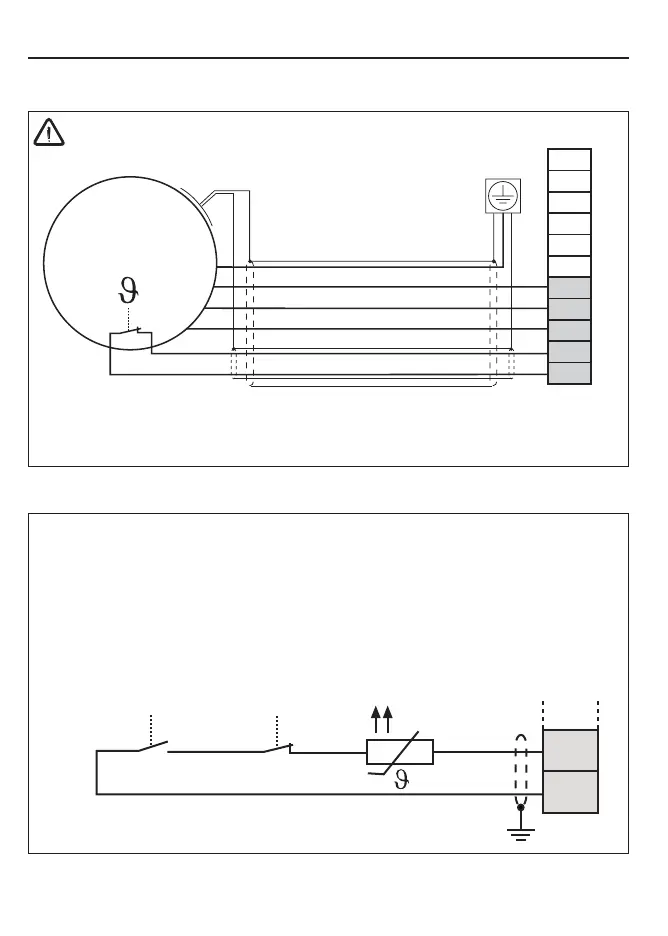
3.3.5 External temperature monitoring
T1
K1
12 11
T2
• Terminals T1, T2
• Tripping resistance 1.65...4 kOhm
• Reset resistance 0.75...1.65 kOhm
• Design in accordance with VDE 0660 Part 302
• This function can be activated by the machine builder by software
• Do not lay connecting cable together with control cable
• Permissible in the motor cable only with double shielding
• Connect relay K1 for fire prevention in regenerative operation (see 3.3.6)
Motor-PTC
Other
Installation and Connection
3.3.4 Motor connection
• max. motor line length see chapter 2.3
Apply shieldings over a large
contact surface of the mounting
plate
Motor-PTC
(optionally)
 Loading...


