EasyManuals Logo
Home>KEB>DC Drives>COMBIVERT F5 Series

KEB COMBIVERT F5 Series Installation Guideline

KEB COMBIVERT F5 Series
30 pages
To Next Page IconTo Next Page
To Previous Page IconTo Previous Page
Page #17 background imageLoading...
Page #17 background image
43
22
23
24
25
26
27
28
29
X2A
17
18
19
20
21
11
12
13
14
15
16
10
1
2
3
4
5
6
7
8
9
U
+
1
2
7
8
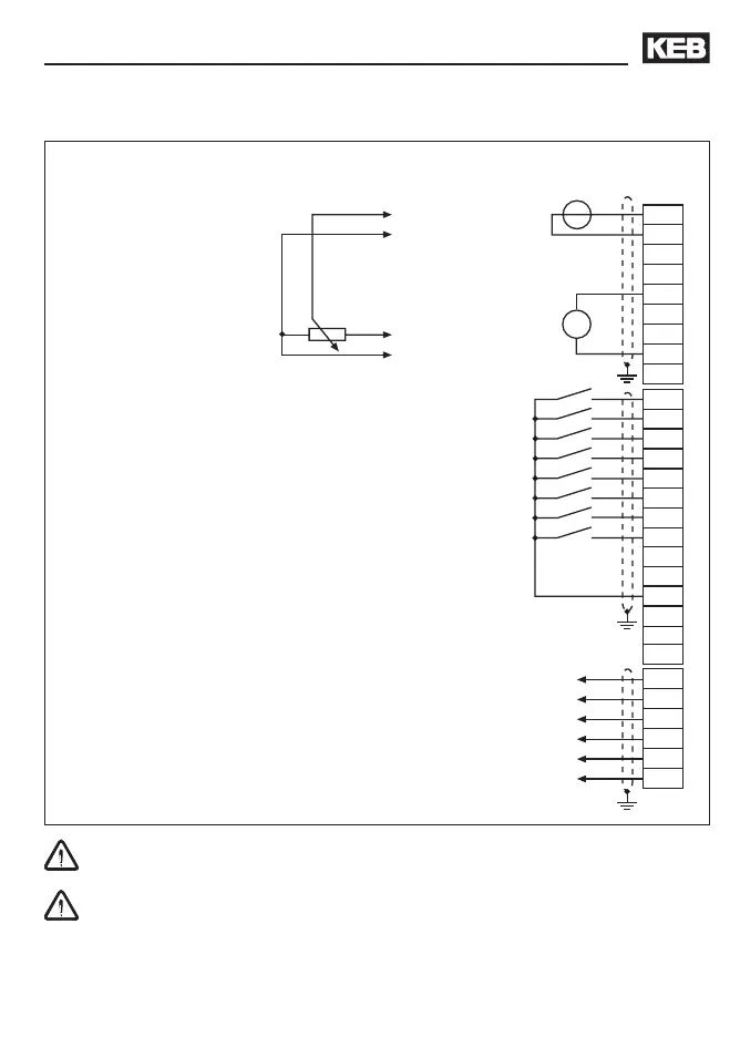
Installation and Connection
3.5.2 Connection of the control terminal strip
Set value
potentiometer
3...10 kOhm
Set value signal
0...±10 V DC
Analog output
±10 V DC /
max.5 mA
max. 30 V / 1 A DC
max. 30 V / 1 A DC
To avoid interferences a separate shielding must be provided for analog and digital control
lines. Depending on the use of the relay outputs, an extra shielding is to be used, too.
In case of inductive load on the relay outputs a protective wiring must be provided (e.g.
free-wheeling diode)!

Other manuals for KEB COMBIVERT F5 Series

Questions and Answers:

Question and Answer IconNeed help?

Do you have a question about the KEB COMBIVERT F5 Series and is the answer not in the manual?

KEB COMBIVERT F5 Series Specifications

General IconGeneral
BrandKEB
ModelCOMBIVERT F5 Series
CategoryDC Drives
LanguageEnglish

Related product manuals