42
3.5 Control Board Compact/General
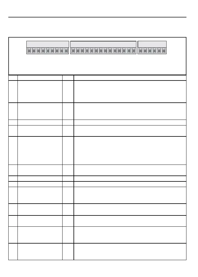
3.5.1 X2A Control Terminal Strip
• Tightening torque 0,22...0,25 Nm (2 lb inches)
• Use shielded/drilled cables
• Lay shield on one side of the inverter onto earth potential
Installation and Connection
123456789
10 11 12 13 14 15 16 17 18 19 20 21
22 23 24 25 26 27 28 29
PIN
Function Name Description
1
+ Set value input AN1+ Differential voltage inputs 0...±10 VDC; Ri = 55kOhm
2
- Set value input AN1- AN1: Setting of the analog set value
3
+ Analog input AN2+ AN2: no function at KEB factory settings
4
- Analog input AN2-
Progr. analog outputs 0...±10 VDC / max. 5 mA; defined by the manufacturer
5
Analog output 1 AO1 Output of the actual output frequency 0...±100 Hz
6
Analog output 2 AO2 Output of the apparent current 0...2 x I
N
7
+ 10 V Output CRF Reference voltage for set value poti (max. 4 mA)
8
Analog Mass COM Mass for analog in- and outputs
9
Analog Mass COM Mass for analog in- and outputs
Prog. Digital inputs Function of the inputs is defined by the manufacturer
10
Fixed frequency 1 (CP.19) I1 13...30 VDC ±0% smoothed; Ri: 2,1 kOhm; scan time 1 ms
11
Fixed frequency 2 (CP.20) I2 I1 + I2 = Fixed frequency 3 (CP.21)
12
External fault I3 Input for external fault setting (E.EF)
13
DC-braking I4 Activates the DC-braking (CP.22/23)
14
Forward F Preset rotation;
15
Reverse R Forward has priority
16
Control release/ Reset ST Power modules are enabled; reset at opening
17
Reset RST Reset; only when an error occurs
Digital outputs max. 50 mA; function is defined by the manufacturer
18
Transistor output 1 O1 switched at factual = fset
19
Transistor output 2 O2 Ready signal (switched as long as no error occurs)
20
24 V-Output U
out
Supply of the programmable inputs
21
20...30 V-Input U
in
Voltage input for external supply
22
Digital Mass 0V Potential for digital in- /outputs
23
Digital Mass 0V Potential for digital in- /outputs
24
Relay 1 / NO contact RLA Programmable relay output (CP.31)
25
Relay 1 / NC contact RLB Load ability max. 30 VDC / 1A
26
Relay 1 / switching contact RLC Factory setting: Fault relay
27
Relay 2 / NO contact FLA Programmable relay output (CP.32)
28
Relay 2 / NC contact FLB Load ability max. 30 VDC / 1A
29
Relay 2 / switching contact FLC Factory setting: Frequency dependent switch
 Loading...


