33
Site altitude max. 2000m. With site altitudes over 1000m a power reduction of 1% per
100m must be taken into consideration.
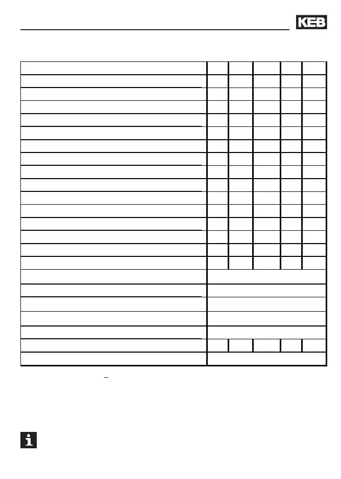
2.3.2 400 V-class
Product Description
12 13 14 15 16
EE EEE
33 333
[kVA] 6,6 8,3 11 17 23
[kW] 4 5,5 7,5 11 15
[A] 9,5 12 16,5 24 33
[A] 17 21,6 29,7 36 49,5
[A] 21 25,9 35,6 43 59
[A]1317 233143
[A] 20 25
25 35 50
[kHz] 16 16 8 4 2
[kHz] 16 16 16 16 4
[W] 300 250 320 350 330
[Ohm]8239 39 3925
[Ohm] 150 110 85 56 42
[A]1021 212132
[V] 305...500 ±0
[Hz] 50 / 60 ±2
[V]
400
1)
[V] 3 x 0...U
N
[Hz] 0...400
[mm²] 2,5 4 4 6 10
[m] 100
Inverter Size
Housing size
Phases
Output rated power
Max. rated motor power
Output rated current
Max. short time current
OC-tripping current
Input rated current
Max. permissible mains fuse (inert)
Rated switching frequency
Max. switching frequency
Power loss at rated operation
Min. braking resistor
Typ. braking resistor
Max. braking current
Mains voltage U
N
Mains frequency
Input rated voltage
Output voltage
Output frequency
Min. motor line cross section
Max. motor line length (shielded)
1)
at mains voltage > 460 V multiply the nominal current with factor 0.86