39
Installation and Connection
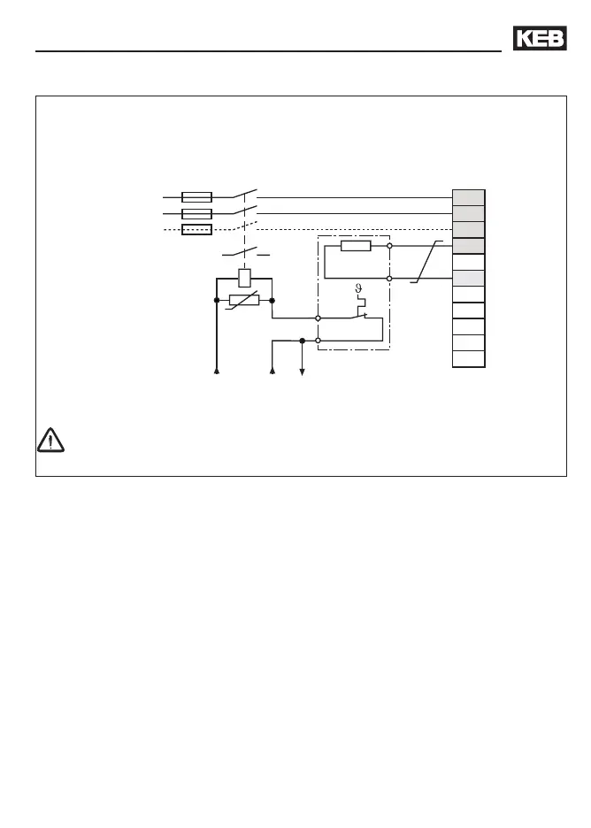
3.3.6 Connection of the braking resistor with temperature monitoring
U
V
W
PB
L3
N/L2
X1A
T1
T2
--
L1
++
PA
PB
OH1
OH2
U
K1
1112
• PA, PB Connector for braking resistor (see chapter 2.2)
• Technical data (see chapter 2.3)
• During clearing of the temperature monitoring the input voltage is switched off
• for additional protection in regenerative operation connect the auxiliary contacts 11
and 12 of the line contactor K1 (see 3.3.5)
Braking resistors can develop very high surface temperatures, therefor install as safe-to-
touch as possible.
230 or 24 V AC/DC
drive
at 24 V AC/DC
check tripping
 Loading...


