40
157810111415162022
24 25 26 27 28 29
Installation and Connection
3.4 Control Board Basic
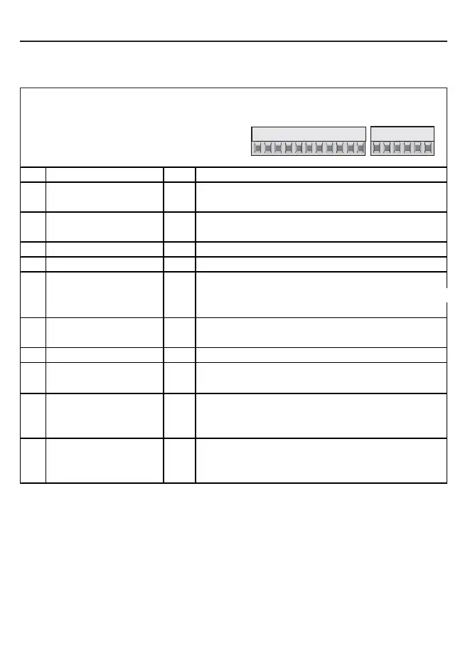
3.4.1 X2A Control Terminal Strip
• Tightening torque 0,22...0,25 Nm (2 lb inches)
• Use shielded/drilled cables
• Lay shield only on the inverter side onto
earth potential
X2A
PIN
Function Name Description
1
+ Set value input AN1+ Differential voltage inputs 0...±10 VDC; Ri = 55kOhm
2
- Set value input AN1- AN1: Setting of the analog set value
Progr. analog outputs 0...±10 VDC / max. 5 mA; defined by the manufacturer
5
Analog output 1 AO1 Output of the actual output frequency 0...±100 Hz
7
+ 10 V Output CRF Reference voltage for set value poti (max. 4 mA)
8
Analog Mass COM Mass for analog in- and outputs
Prog. Digital inputs Function of the inputs is defined by the manufacturer
10
Fixed frequency 1 (CP.19) I1 13...30 VDC ±0% smoothed; Ri: 2,1 kOhm; scan time 2 m
11
Fixed frequency 2 (CP.20) I2 I1 + I2 = Fixed frequency 3 (CP.21)
14
Forward F Preset rotation;
15
Reverse R Forward has priority
16
Control release/ Reset ST Power modules are enabled; reset at opening
20
24 V-Output U
out
Supply of the programmable inputs
22
Digital Mass 0V Potential for digital in- /outputs
24
Relay 1 / NO contact RLA Programmable relay output (CP.31)
25
Relay 1 / NC contact RLB Load ability max. 30 VDC / 1A
26
Relay 1 / switching contact RLC Factory setting: Fault relay
27
Relay 2 / NO contact FLA Programmable relay output (CP.32)
28
Relay 2 / NC contact FLB Load ability max. 30 VDC / 1A
29
Relay 2 / switching contact FLC Factory setting: Frequency dependent switch
 Loading...


